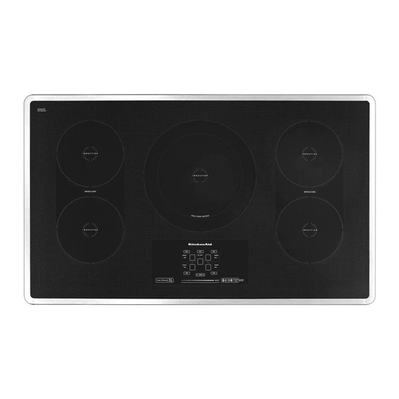
KitchenAid KICU569XSS Installationsanleitung Handbuch - Seite 7
Blättern Sie online oder laden Sie pdf Installationsanleitung Handbuch für Kochfeld KitchenAid KICU569XSS herunter. KitchenAid KICU569XSS 16 Seiten. 30" (76.2 cm) and 36" (91.4 cm) electric
Auch für KitchenAid KICU569XSS: Produktabmessungen (1 seiten), Handbuch der Abmessungen (8 seiten), Installationshandbuch (16 seiten)

Electrical Shock Hazard
Disconnect power before servicing.
Use 8 gauge copper wire.
Electrically ground cooktop.
Failure to follow these instructions can result in death,
fire, or electrical shock.
This cooktop is manufactured with a frame-connected, green (or
bare) ground wire.
1. Disconnect power.
2. Remove junction box cover if it is present.
3. Connect the flexible cable conduit from the cooktop to the
junction box using a UL listed or CSA approved conduit
connector.
A
A. UL listed or CSA approved conduit connector
4. Tighten screws on conduit connector if present.
5. See "Electrical Connection Options Chart" to complete
installation for your type of electrical connection.
Electrical Connection Options chart
If your home has:
4-wire
(1.3 cm)
3-wire
½"
(1.3 cm)
05-Sep-2019 13:08:05 EDT | RELEASED
Make Electrical Connection
WARNING
Go to Section:
4-Wire Cable from Home
Power Supply
½"
3-Wire Cable from Home
Power Supply
In some European factories the letter "W" of the part code mentioned herein will be automatically
4-Wire Cable from Home Power Supply
IMPORTANT: Use the 4-wire cable from home power supply in
the U.S.A. where local codes do not allow grounding through
neutral, New Branch circuit installations (1996 NEC), mobile
homes and recreational vehicles, new construction, and in
Canada.
A
B
C
D
A. Cable from home power supply
B. Red wires
C. Green (or bare) ground wires
D. 3-Wire cable from cooktop
E. Junction box
1. Connect the 2 red wires (B) together using a UL listed wire
connector.
2. Connect the green (or bare) ground wire (C) from the cooktop
cable to the green (or bare) ground wire (in the junction box)
using a UL listed wire connector.
3. Put a UL listed wire connector on the end of the white
wire (F).
NOTE: Do not connect the green (or bare) ground wire to the
neutral (white) wire in the junction box.
4. Connect the 2 black wires (H) together using a UL listed wire
connector.
5. Install junction box cover.
replaced by the number "4000" (e.g. "W12345678" becomes "400012345678")
E
F
G
H
I
F. White wire (from home power
supply)
G. UL listed wire connector
H. Black wires
I. UL listed or CSA approved
conduit connector with wire
bushing
7
