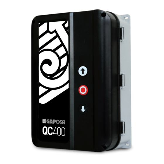
GAPOSA QC400 Handbuch - Seite 6
Blättern Sie online oder laden Sie pdf Handbuch für Motor GAPOSA QC400 herunter. GAPOSA QC400 16 Seiten. Automatic control unit for three/single-phase motors with digital or mechanical limits

1 INSTALLATION
For a correct installation:
• Install where the control unit can be protected from rain or adverse weather conditions
• Mounting must be vertical
• The mounting surface must be flat and not be subject to vibrations
• Do not install in an area of potential risk of condensation
• It is important that the door can be clearly seen from the position of the control while operating
• Install in an area not accessible to children or unauthorized persons
• Do not perform any electrical connections before the installation is completely accomplished
2 ELECTRICAL OPERATING INSTRUCTIONS
Read carefully and respect the connection's sequence. IMPORTANT! All the connection operations must be performed
only after the main power supply has been disconnected. TURN OFF THE MAIN POWER SWITCH BEFORE ANY OTHER
OPERATION!
When connecting control to mains supply a mains isolator switch (16A CEE - plug) according EN 12453 is required.
The supply disconnect device (main switch or CEE plug) must be installed between 0.6 m and 1.7 m above floor level.
2.1 CONTROL UNIT POWER SUPPLY
The control unit can be powered in tree different modes: 400V~ 3-phase, 230~ 3-phase or 230V~ 1-phase.
WARNING! The installation must include an automatic cut off switch with minimum distance between the contacts of at
least 3 mm.
WARNING: The power supply of the motor and of the control unit must be the same. Otherwise you can damage the mo-
tor and the control unit and put at risk the safety of the installer.
1x230VAC (L1, N, PE)
VOLTAGE
SELECT
X1
L1
L1
X2
L2(N)
N
L3
PE
X3
PE
If you need to disconnect the power cable and then to reconnect it or change the control unit wiring sequence, you HAVE TO
connect the wires properly, restoring the original configuration. Take care to connect the ground wire to the X3 terminal.
WARNING! Verify the direction of rotation of the motor supplied with 3ph x 400V or 1ph x 230V: pay attention to the direc-
tion of rotation of the motor: by pressing the OPEN button (S1) the door has to open while, by pressing the CLOSE button
(S2), the door must close. In case of wrong direction, reverse two of the phases (L1, L2 and L3) on the X2 terminal or U
(OPEN) and W (CLOSE) on X4 terminal.
2.2 CONNECTING THE CONTROL UNIT TO THE MOTOR
After the motor and control are fitted they can be connected with a plug-in cable.
The cable has plugs on each end for an
easy fitting.
The plugs for motor and control panel are
different and cannot be interchanged.
6
3x230VAC (L1, L2, L3, PE)
WRONG JUMPER
VOLTAGE
PLACEMENT
SELECT
CAN DESTROY
THE CONTROL
X2
L2(N)
1 PHASE
230VAC
MAINS
CEE PLUG
X3
V = COMMON
WRONG JUMPER
PLACEMENT
CAN DESTROY
X1
THE CONTROL
L1
L1
L2
3 PHASE
230VAC
L3
L3
MAINS
CEE PLUG
PE
PE
N required ONLY for services - see par. 7/9
1 phase
230V Motor
M
U = OPEN
W = CLOSE
PE
M
3~ 230V
3~ 400V
Motor
NOTE: PE must be connected first and disconnected last
PE
if motor plug-in terminals are disconnected
3x400VAC (L1, L2, L3, PE)
VOLTAGE
SELECT
X1
L1
X2
L2(N)
L3
X3
PE
U
V
W
SAFETY
U
JUMPER
X4
V
W
WRONG JUMPER
PLACEMENT
CAN DESTROY
THE CONTROL
L1
L2
3 PHASE
400VAC
L3
MAINS
CEE PLUG
PE
U
V
W
PE
X3
