GAPOSA XQ60 Anleitung Handbuch - Seite 5
Blättern Sie online oder laden Sie pdf Anleitung Handbuch für Motor GAPOSA XQ60 herunter. GAPOSA XQ60 8 Seiten. Tubular motors with mechanical limit switch and integrated receiver.
Auch für GAPOSA XQ60: Anleitung Handbuch (8 seiten), Anweisungen (4 seiten), Handbuch (15 seiten), Anleitung Handbuch (13 seiten), Handbuch (13 seiten), Handbuch (16 seiten)
►DESCRIPTION
EN
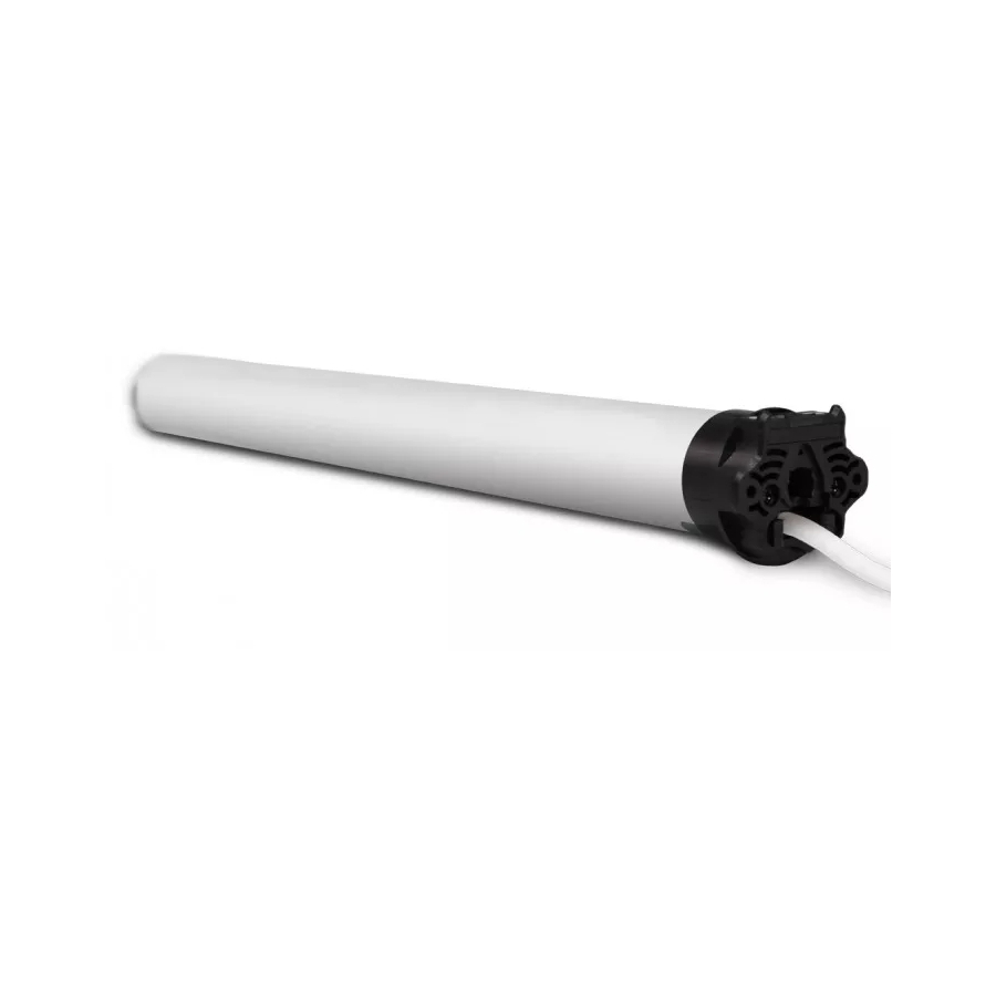
Tubular motor designed for rolling shutters, blinds and awnings.
It features an integrated receiver (434,15MHz) with remote limit setting
and remote user programmable intermediate stop. It works with GAPOSA
transmitters.
Motor's memory capacity: maximum of 28 transmitters.
Transmitters' range: 20 m indoor and 200 m outdoor.
►INSTALLATION (Fig. 1)
WARNING: Tubular motor must be always installed in the tube first before
putting it into action since the electronic control of the speed variation do not
enable the motor to turn if the limit switch drive do not turn with it.
WARNING: The mounting distance between two motor heads should not
be less than 1/2m;
To complete installation, the motor must be provided with a couple of adaptors
(corresponding with the tube) and a fixing bracket. For a list of the available
accessories, refer to the catalogue.
WARNING: incorrect installation can cause serious injuries. Follow the
installation instructions. Before you remove all unnecessary cables and turn
off any equipment not required for this operation.
• Fix the adaptors to the motor distinguishing the limits ring (Fig. 1.1 A) from
the drive pulley ( (Fig. 1.2 B).
• Turn and lock the clip after inserting it in the drive-shaft groove.
• The fixing bracket (C) must be fixed inside the box or on the awning frame so
that the roller tube (F) is perfectly horizontal and at a height not less than 1,8m.
• Insert the motor (E) into the tube (F) until its end stops against the limits ring.
• [FOR XQ50] Place the motor square pin (D) on the bracket (C) and the cap at the
opposite end of the tube on the fixing plate.
WARNING:
• Never hit on the head of the motor (D) when you insert it into the tube.
• For the 50 range, with torque up to 15Nm, the minimum tube diameter is
50x1,5mm; for motors with higher torques, the minimum tube diameter is
60x1,5mm.
• For the 60 range, the minimum tube diameter is 63x1,5mm.
• The screws used to fix the last slat on the tube may be too long and
reach the tubular part of the motor. Use appropriate screws or fixing
clips.
• Motor moving parts installed under 2,5m from the ground must be
protected.
• A wrong motor installation can damage persons or objects.
►WIRING (Fig. 2)
Check that the mains voltage available on the system is as shown on the label. The
motor mains connection should be executed according to the diagram on the next
page, by qualified technicians able to operate in compliance with the rules.
ATTENTION: The power supply must contemplate a switching device with an
opening distance between contacts of at least 3mm.
For the models XQ50 and XQ60 with limit switches without manual override
and supplied without cable, use one of the following types available
in GAPOSA: H05VV-F 3Gx0,75mm
3Gx0,75mm
(for outdoor instalations) (Fig. 5).
2
For models XQ50 and XQ60 with limit switches without manual override, in
case the supply cable is damaged, it must be replaced by another cable or a
special set available by the manufacturer or his technical assistance (fig. 5).
• If the motor runs the wrong way round (es.: the shutter/awning closes with
the up control or the other way round) the external cables must be reversed.
• Do not connect more than one tubular motor to a single switch.
• Do not set the shutter/awning into motion while you are cleaning or
servicing the device and disconnect the supply.
• The switch controlling the motor must be installed in full view, not higher
than 1,5m and it must be kept far from moving parts.
►PROGRAMMING PROCEDURE IN INSTALLATION MADE UP OF SEVERAL XQ
PZ [only for XQ50]
If the installation is made up of several XQ-PZ, only one PZ motor must be powered
during programming. All the other motors must be disconnected in order to avoid
interferences
►PROGRAMMING TRANSMITTER
CAUTION: If more motors with receiver have to be installed,
it is important to power up only one motor at time during the first
programming session, in order to avoid any interferences with the others.
1. Power up the motor to be programmed.
2. Hold PROG-TX pressed until the motor starts moving.
3. Check the rotation of the motor, then release PROG-TX (the motor stops).
4. Within 5 seconds press the corresponding button (i.e. UP if the motor
rotates upwards or DOWN if vice versa).
In this way the transmitter has been programmed and the rotation of the motor
has been syncronized.
(for indoor installations) or H05RN-F
2
►ADDING TRANSMITTER
1. Hold PROG-TX pressed until the motor starts moving.
2. Check the rotation of the motor, then release PROG-TX (the motor stops).
3. Within 5 seconds press the corresponding button (i.e. UP if the motor
rotates upwards or DOWN if vice versa) of a new transmitter.
In this way the new transmitter has been added and programmed and the
rotation of the motor has been syncronized.
►CHECKING / CHANGING DIRECTION
1. Press UP or DOWN the motor should go UP or DOWN, otherwise to change
direction:
2. Press and hold PROG-TX buttontill the motor starts moving.
3. Press STOP: The motor makes a brief jog.
Direction of the motor has been reversed.
IMPORTANT: change direction must be performed before starting limit
setting otherwise limits must be reset
►RESET TRANSMITTER MEMORY (DELETING ALL THE TRANSMITTERS OR
CHANNELS OR SENSORS)
Option 1
Using an already programmed transmitter press and hold both PROG-TX and
STOP buttons till the motor makes first a brief jog and, after a while, a second
long jog. Memory is now empty.
Option 2
1. Without an already programmed transmitter switch the motor power supply
OFF. Then switch it ON.
2 Within 8 seconds, using any 434,15 Gaposa transmitter, press and hold both
PROG-TX and STOP buttons until the motor makes a long jog. Memory is
now empty.
►SETTING THE END LIMITS
Motors are supplied with pre-set limit switches, in order to allow two turns in both
directions.
IMPORTANT: Limit-switches setting procedures shown are valid for right
and left side installation.
IMPORTANT: The procedure shown is valid for shutters installed in internal
boxes and for awnings with rear-motor winding. In case shutters are in an
external box or awnings wind front-motor, the setting-screws must be read
reversed (ex.: up as down and vice versa).
N.B.: Arrows A indicate the direction of rotation controlled by each
adjusting screw. Arrows B indicate the screw direction for increasing (+) or
decreasing (-) revolutions controlled by the limit-switches.
1. After installation and before fixing the shutter/awning at the tube, activate
the motor downwards until it stops.
ATTENTION: Check that the motor/tube turns in the right direction.
2. Turn the lower screw to (+) so that the tube reaches the best position for
its connection with the shutter/awning (Fig. 3.1).
3. Fixing the shutter/awning at the tube and then turn the lower adjusting
screw to (-) or (+) in order to set the exact desired "down" position
(Fig. 3.2).
4. Open the shutter/roll up the awning until it does not stop and then turn
the upper screw to (+) till the shutter/awning reaches the exact desired
"up" position Fig. 3.3).
In case you need to correct the "up" limit position, because it's over, close
the shutter/roll the awning down) shortly, then turn the upper adjusting
screw to (-).
Repeat then the sequences from point 3.
► MANUAL OVERRIDE (Range M) - Fig. 6
Motor with manual override in some installation examples
IMPORTANT:
• The motor with manual override must be installed orthogonal to the
fixing plate and in a roller tube perfectly horizontal.
• The manual override device on the head of the motor (cardan-joint
with eye or shaft with eye) must be fixed not higher than 1,8m.