GAPOSA XQ60 Anweisungen - Seite 3
Blättern Sie online oder laden Sie pdf Anweisungen für Jalousien GAPOSA XQ60 herunter. GAPOSA XQ60 4 Seiten. Tubular motors with mechanical limit switch and integrated receiver.
Auch für GAPOSA XQ60: Anleitung Handbuch (8 seiten), Handbuch (15 seiten), Anleitung Handbuch (13 seiten), Handbuch (13 seiten), Handbuch (16 seiten), Anleitung Handbuch (8 seiten)
►DESCRIPTION
EN
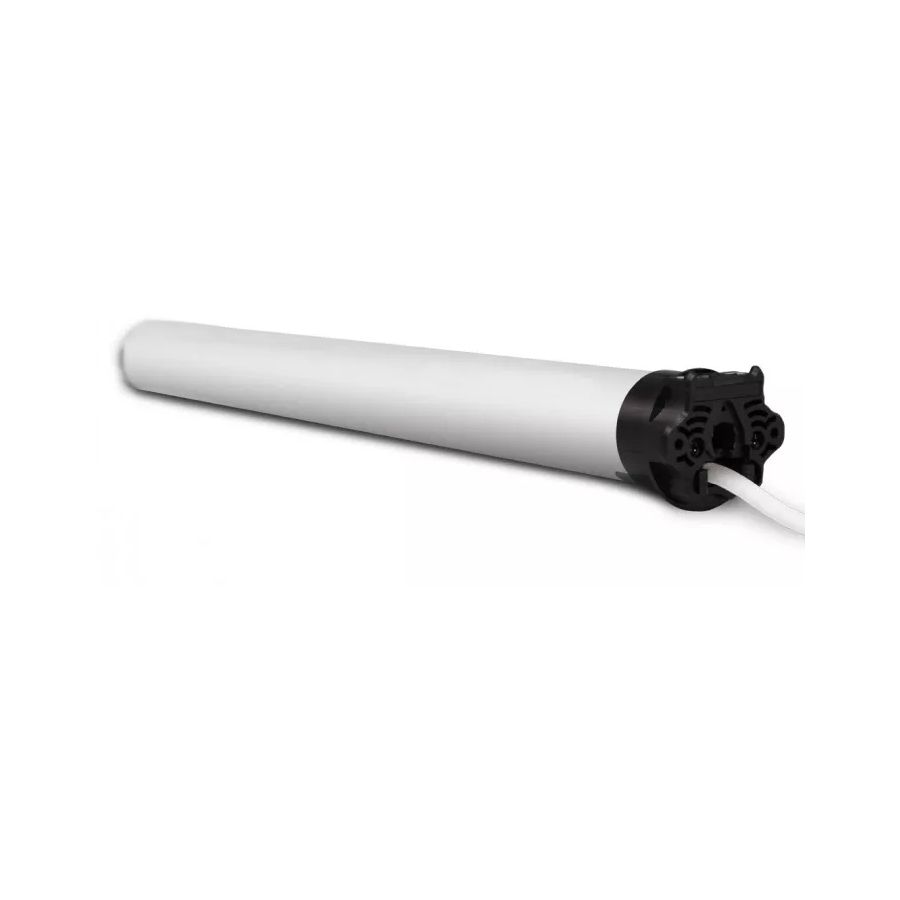
Tubular motor for roller shutters and awnings for intermittent use (working time:
4 minutes before the thermal protector intervention). The torque of each model is
indicated on the relative label. Check that torque and working time stated on the
label are compatible with the shutter/awning that must be motorized.
►INSTALLATION (Fig. 1)
To complete installation, the motor must be provided with a couple of adaptors (correspon-
ding with the tube) and a fixing bracket. For a list of the available accessories, refer to the
catalogue.
WARNING: incorrect installation can cause serious injuries. Follow the installation
instructions. Before you remove all unnecessary cables and turn off any equipment
not required for this operation.
• Fix the adaptors to the motor distinguishing the limits ring (Fig. 1.1 A) from the drive pulley
( (Fig. 1.2 B).
• Turn and lock the clip after inserting it in the drive-shaft groove.
• The fixing bracket (C) must be fixed inside the box or on the awning frame so that the roller
tube (F) is perfectly horizontal and at a height not less than 1,8m.
• Insert the motor (E) into the tube (F) until its end stops against the limits ring.
• [FOR XQ50] Place the motor square pin (D) on the bracket (C) and the cap at the opposite
end of the tube on the fixing plate.
WARNING: Never hit on the head of the motor (D) when you insert it into the tube.
• For the XQ50, with torque up to 15Nm, the minimum tube diameter is 50x1,5mm;
for motors with higher torques, the minimum tube diameter is 60x1,5mm.
• For the XQ60, the minimum tube diameter is 63x1,5mm.
WARNING:
• The screws used to fix the last slat on the tube may be too long and reach the tubu-
lar part of the motor. Use appropriate screws or fixing clips.
• Motor moving parts installed under 2,5m from the ground must be protected.
• A wrong motor installation can damage persons or objects.
►ELECTRICAL CONNECTION (Fig. 2)
Check that the mains voltage available on the system is as shown on the la-
bel. The motor mains connection should be executed according to the diagram on the next
page, by qualified technicians able to operate in compliance with the rules.
ATTENTION: The power supply must contemplate a switching device with an opening
distance between contacts of at least 3mm.
For the models XQ50 and XQ60 with limit switches without manual override and supplied
without cable, use one of the following types available in GAPOSA: H05VV-F 4Gx0,75mm
(for indoor installations) or H05RN-F 4Gx0,75mm
For models XQ50 and XQ60 with limit switches without manual override, in case the supply
cable is damaged, it must be replaced by another cable or a special set available by the manu-
facturer or his technical assistance (fig. 5).
• If the motor runs the wrong way round (es.: the shutter/awning closes with the up control or
the other way round) the external cables must be reversed.
• Do not connect more than one tubular motor to a single switch.
• Do not set the shutter/awning into motion while you are cleaning or servicing the device
and disconnect the supply.
• The switch controlling the motor must be installed in full view, not higher than 1,5m and it
must be kept far from moving parts.
►SETTING THE LIMITS SWITCHES (Fig. 3)
Motors are supplied with pre-set limit switches, in order to allow two turns in both directions.
IMPORTANT: Limit-switches setting procedures shown are valid for right and left side
installation.
IMPORTANT: The procedure shown is valid for shutters installed in internal boxes
and for awnings with rear-motor winding. In case shutters are in an external box or
awnings wind front-motor, the setting-screws must be read reversed (ex.: up as down
and vice versa).
N.B.: Arrows A indicate the direction of rotation controlled by each adjusting screw.
Arrows B indicate the screw direction for increasing (+) or decreasing (-) revolutions
controlled by the limit-switches.
1. After installation and before fixing the shutter/awning at the tube, activate the motor
downwards until it stops.
ATTENTION: Check that the motor/tube turns in the right direction.
2. Turn the lower screw to (+) so that the tube reaches the best position for its connection with
the shutter/awning (Fig. 3.1).
3. Fixing the shutter/awning at the tube and then turn the lower adjusting screw to (-) or (+) in
order to set the exact desired "down" position (Fig. 3.2).
4. Open the shutter/roll up the awning until it does not stop and then turn the upper screw to
(+) till the shutter/awning reaches the exact desired "up" position Fig. 3.3).
In case you need to correct the "up" limit position, because it's over, close the shutter/roll the
awning down) shortly, then turn the upper adjusting screw to (-). Repeat then the sequences
from point 3.
►MANUAL OVERRIDE (Range M) - Fig. 6
Motor with manual override in some installation examples
IMPORTANT:
• The motor with manual override must be installed orthogonal to the fixing plate
and in a roller tube perfectly horizontal.
• The manual override device on the head of the motor (cardan-joint with eye or
shaft with eye) must be fixed not higher than 1,8m.
2
(for outdoor instalations) (Fig. 5).
►DESCRIPTION
FR
Motoréducteur tubulaire pour volet/store/rideau à usage intermittent (temps de
fonctionnement: 4 minutes avant l'intervention du protecteur thermique). Pour le
couple de torsion il faut se référer à ce qu'il est indiqué sur l'étiquette de chaque
modèle. Il faut vérifier que le couple et le temps de fonctionnement indiqués sur
l'étiquette soient compatibles avec le volet/store/rideau à motoriser.
►INSTALLATION (Fig. 1)
Pour l'installation, le motoréducteur doit être pourvu d'un jeu d'adaptateurs (correspondants
avec le tube) et d'un support. Pour les accessoires veuillez consulter notre catalogue de vente.
ATTENTION: une installation non correcte peut causer de graves accidents. Suivez to-
utes les instructions d'installation. Avant l'installation il faut éliminer tous les câbles
inutiles et désactiver tout appareillage présent et qui n'est pas nécessaire pour le
fonctionnement.
• Insérez les adaptateurs sur le motoréducteur en distinguant la bague de la fin de course (Fig.
1.1 A) de la couronne d'entraînement (Fig. 1.2 B).
• Le support du motoréducteur (C) doit être fixé à l'intérieur du caisson ou sur l'armature du
store de manière que le tube (F) soit en position parfaitement horizontale et à une hauteur
non inférieure à 1,8m.
• Insérez le motoréducteur (E) dans le tube (F) jusqu'à ce que l'extrémité de cela soit sur la
butée de la bague du fin de course (A) (Fig. 1.3).
• [POUR XQ50] Insérez le carré de soutien (D)du motoréducteur dans le support et l'em-
bout dans l'extrémité opposée du tube, dans son support.
ATTENTION: ne frappez jamais le carré du moteur pour l'introduire dans le tube.
• Pour la XQ50, avec couple jusqu'à 15Nm, le diamètre min. du tube est de 50x1,5mm;
pour couples plus élevés, le diamètre min. est de 60x1,5mm.
• Pour la XQ60, le diamètre min. du tube est de 63x1,5mm.
ATTENTION:
• Les vis de fixation de la lame au tube ne doivent en aucun cas toucher le corps du
moteur. Utiliser des vis courtes ou des agrafes de fixation.
• Il faut protéger toutes les parties en mouvement du moteur qui se trouvent au-
dessous de 2,5m de terre.
• Une installation inadéquate du motoréducteur peut causer des dommages aux
personnes et aux éléments extérieurs.
►BRANCHEMENT ELECTRIQUE (Fig. 2)
Vérifier que la tension d'alimentation disponible est celle indiquée sur
l'étiquette. Le branchement du motoréducteur au réseau de l'alimentation doit être
exécuté selon le schéma à la page qui suit, par des techniciens qualifiés capables d'opérer en
respectant les normes.
ATTENTION: le réseau de l'alimentation doit être pourvu d'un dispositif de
2
sectionnement et la distance d'ouverture entre les contacts doit être d'au
moins 3mm.
Pour les modèles XQ50 et XQ60 avec fin de courses sans manœuvre de secours et fournis
sans câble, utilisez l'un des deux types de câbles suivants et disponibles chez GAPOSA:
H05VV-F 4Gx0,75mm
(pour des installations à l'intérieur) ou H05RN-F 4Gx0,75mm
2
installations à l'extérieur) (Fig. 5).
Pour les modèles XQ50 et XQ60 avec fins de courses sans manoeuvre de secours, si le câble
d'alimentation est endommagé, il doit être remplacé par un autre câble ou un kit spécial
disponible chez le constructeur ou chez son service d'assistance technique (Fig. 5).
• Si le motoréducteur tourne dans le sens inverse (le volet/store/rideau se ferme à la comman-
de d'ouverture ou le contraire) il faut inverser les fils externes.
• Ne branchez jamais deux ou plusieurs moteurs à un interrupteur.
• Ne jamais actionner le volet/store/rideau pendant le nettoyage ou l'entretien du dispositif
et déconnectez l'alimentation.
• Le bouton qui actionne le dispositif doit être installé en vue, à une hauteur non supérieure à
1,5m et à l'écart d'objets en mouvement.
►RÉGLAGE DES FINS DE COURSES (Fig. 3)
Le motoréducteur est livré avec les fins de courses préréglés à environs deux tours dans
chaque sens de rotation.
IMPORTANT: Les procédures de réglage qui suivent sont valables pour l'installation
du motoréducteur à droite ou à gauche du tube.
La procédure décrite est valide dans le cas de volets avec caisson interne et stores
avec enroulement retro-moteur. Dans la cas de volets avec caisson externe ou stores
avec enroulement front-moteur, les vis de réglage des fins des courses doivent se lire
de manière inversée (ex: supérieure pour inférieure et vice versa).
N.B.: les flèches A indiquent quel sens de rotation est contrôlé par chaque vis. Les
flèches B indiquent le sens de rotation pour augmenter (+) ou diminuer (-) le nombre
de tours contrôlés par le fin de course.
1. Une fois l'installation accomplie et avant de fixer le volet/store/rideau au tube,
faire tourner le motoréducteur dans le sens de la descente/déroulement jusqu'à son arrêt.
ATTENTION: Vérifier que le sens de rotation du tube est correct.
2. En agissant sur la vis de réglage inférieure, tournez-la dans le sens (+) pour porter le tube
dans la position la plus pratique pour la fixation du volet/store/rideau.
3. Fixer le volet/store/rideau au tube et, en agissant sur la vis de réglage inférieure, tournez-la
dans le sens (-) ou dans le sens contraire (+) pour régler exactement la position de la fin de
course "bas".
4. Faire tourner le volet/store/rideau vers le haut jusqu'à son arrêt et puis, en agissant sur la vis
de réglage haute, tournez-la dans le sens (+) jusqu'à la position d´arrêt "haut" souhaitée.
Pour corriger la position du fin de course "haut", si trop éloignée, actionner le motoréducteur
dans le sens de la descente/déroulement pour un bref moment puis, en agissant sur la vis de
réglage haute, tournez-la dans le sens (-).
Reprendre la procédure du point 3.
►MANOEUVRE DE SECOURS (sur version M) - Fig. 6
Motoréducteur avec manœuvre de secours: différentes possibilités de montage.
IMPORTANT:
• le motoréducteur avec manoeuvre de secours doit impérativement être monté
orthogonalement au support et sur un tube monté parfaitement horizontalement.
• L'élément de commande (anneau ou crochet) fixé au dispositif de manœuvre ma-
nuelle, doit se trouver à une hauteur non supérieure à 1,8m.
(pour des
2