Ikegami ICD-38 Gebrauchsanweisung
Blättern Sie online oder laden Sie pdf Gebrauchsanweisung für Sicherheitskamera Ikegami ICD-38 herunter. Ikegami ICD-38 2 Seiten. Super cube dsp color camera
Auch für Ikegami ICD-38: Spezifikationen (6 seiten), Benutzerhandbuch (6 seiten), Spezifikationen (2 seiten)
INSTRUCTION MANUAL
B/W CAMERA
MODEL
ICD-38
OUTDOOR USE WARNING
WARNING – TO PREVENT FIRE OR
ELECTRIC SHOCK, DO NOT
EXPOSED THIS APPLIANCE TO
RAIN OR MOISTURE.
Ikegami Tsushinki Co., Ltd.
Ikegami Electronics (U.S.A.), Inc.
37 Brook Avenue, Maywood, New Jersey 07607, U.S.A.
Phone: (201) 368-9171, FAX 201-569-1626
Ikegami Electronics (Europe) GmbH
Ikegami Strasse 1, 41460 Neuss 1, F.R. Germany
TEL. 02131-123-0/FAX 02131-102820
Ikegami Electronics (Europe) GmbH U.K. Branch
Kestrel Court, Pound Road, Chertsey, Surrey KT16 8ER, England
TEL. 01-546-7772 & 0932-568966/FAX 0932-569637
The exclamation point within an equilateral triangle is intended to alert
the user to the presence of important operating and maintenance
(servicing) instructions in the literature accompanying the appliance.
NOTE: This equipment has been tested and found to comply with the limits
for a Class A digital device, pursuant to Part 15 of the FCC Rules. These
limits are designed to provide reasonable protection against harmful
interference when the equipment is operated in a commercial environment.
This equipment generates, uses and can radiate radio frequency energy and,
if not installed and used in accordance with the instruction manual, may
cause harmful interference to radio communications. Operation of this
equipment in a residential area is likely to cause harmful interference in which
case the user will be required to correct the interference at his own expense.
CAUTION; ANY CHANGES OR MODIFICATIONS NOT EXPRESSLY
APPROVED BY THE PART RESPONSIBLE FOR COMPLIANCE COULD
VOID THE USERS AUTHORITY TO OPERATE THE EQUIPMENT.
El signo de exclamación en el interior de un triángulo equilátero
tiene la finalidad de avisar al usuario de la presencia de
instrucciones de utilización y mantenimiento (servicio)
importantes en el manual que acompaña al aparato.
NOTA: Este equipo ha sido probado y ha demostrado cumplir con los límites
establecidos para los dispositivos digitales de la clase A, en conformidad con
el Apartado 15 de los Reglamentos de la FCC. Estos límites han sido
diseñados para proporcionar una protección razonable contra la
interferencia perjudicial cuando el equipo sea utilizado en un ambiente
comercial. Este equipo genera, utiliza y puede radiar energía radioeléctrica,
y, si no se instala y usa de acuerdo con las instrucciones de este manual,
puede causar interferencias perjudiciales en las comunicaciones por radio.
La utilización de este equipo en una zona residencial causará
probablemente interferencias perjudiciales, en cuyo caso, el usuario deberá
corregir la interferencia corriendo él con todos los gastos.
PRECAUCIÓN; CUALQUIER CAMBIO O MODIFICACIÓN QUE NO HAYA
SIDO APROBADO EXPRESAMENTE POR LA PARTE RESPONSABLE
PODRÍA ANULAR LA AUTORIZACIÓN QUE TIENE EL USUARIO PARA
UTILIZAR EL EQUIPO.
English
Handling precautions
E-1.
(1) Do not open the camera housing unless absolutely necessary. Otherwise,
the internal precision parts may be damaged, resulting in troubles.
(2) Do not use the camera in any place where it is exposed to water or high
moisture. Preferably use the camera at ambient temperatures of -10 to +50°C.
(3) While moving the camera, be careful not to drop or shock it.
(4) Do not touch the CCD faceplate.
General
E-2.
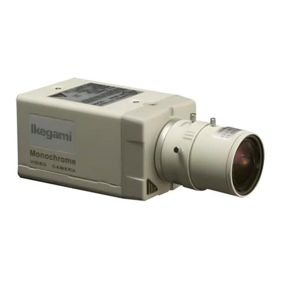
The ICD-38 is a black-and-white camera equipped with a 1/3" CCD imaging
device. This unit features, line lock, automatic electronic shutter control
(AES), backlight compensation (BLC), mirror imaging and 2-way automatic
iris. Its high-sensitivity design enables to monitoring with illuminance as low
as 0.1 lux and is best suited for general-purpose monitoring.
Features
E-3.
(1) High sensitivity and high resolution
The 250,000-pixel, high-sensitivity on-chip micro lens CCD and the high-
performance AGC circuit are incorporated to provide for the resolution of
380 horizontal lines and the minimum subject illuminance of 0.1 lux/F1.4.
(2) Automatic electronic shutter control (AES)
The high-speed electronic shutter has automatic electronic shutter control
for wide range. Even with a fixed iris lens in use, the video output is stable
and equivalent to that with an automatic iris lens of F1.4 thru F60.
(3) Backlight compensation
The backlight compensation circuit is built in to give sharp pictures even
in a back-lit scene using the AES or an automatic iris lens.
(4) 2-way automatic iris function
The selector switch for a video iris lens and a DC iris lens enables use of
K32562
almost all types of CCTV automatic iris lenses.
(5) Mirror image
The mirror image selector is used to invert the right and left of an image.
Indirect monitor shooting with a mirror or inverted images made with a
prism lens can be brought back to normal.
(6) The flange focal distance adjustment mechanism facilitates focus
tracking with a zoom lens in use.
Names of parts and their functions
E-4.
CAMERA
VIODEO
Monochrome
1
4
2
FOCUS ADJ
3
LOCK
Monochrome
VIODEO CAMERA
13
LENS
BLC LEVEL
AC24V60Hz 4W
5
IRIS LEVEL
LL PHASE
MAX40mA
CLASS 2
POWER
VIDEO OUT
AES
OFF
ON
14
BLC
OFF
ON
MIR
NOR
INV
LENS
D C
VIDEO
Lens mount (CS mount)
This is used to mount the lens on the camera. Many types of CS mount
lens can be attached.
Flange focal distance adjuster
The flange focal distance may need readjustment depending on the type
of lens. Readjust the distance also when the focus ring on the lens fails to
put the image in focus.
Flange focal distance lock screw
After finely adjusting the camera's flange focal distance, fix the distance
with this screw.
Holder mounting screw holes
These holes are used to fix the camera on the camera holder. They are
also applicable to general tripods.
NOTE: To attach the camera on a tripod or a camera holder, be sure
to use mounting screws.
(1/4'' -20UNC) that are shorter than 5.5 mm.
Auto iris connector
The connector is specifically used to connect the auto iris lens.
Use the optional auto iris lens control connector plug (E4-191J-100 or
equivalent).
• For the video type auto iris lens
Set the lens selector switch to VIDEO position.
— Connector cable leads —
4
2
1
3
1. Red (power)
2. Not used
3. White (video)
4. Black (shielded)
* Dress the end of the green lead not to allow short-circuit.
• For the DC type auto iris lens
Set the lens selector switch to DC position.
— Connector cable leads —
2
4
1
3
1. Damping coil (-)
2. Damping coil (+)
3. Driving coil (+)
4. Driving coil (-)
(LEFT VIEW)
* Connect the leads as shown above. Refer to the instructions of the
lens.
3
1
(TOP VIEW)
Numbers of connector pins
(RIGHT VIEW)
Backlight compensation level control (BLC LEVEL)
This control adjusts the compensation amount while the backlight
compensation function is on.
6
Iris level control (IRIS LEVEL)
7
This control adjusts the sensitivity with a DC iris lens in use.
8
Line lock phase control (LL PHASE)
15
This control adjusts the phases of the video output and the power line.
(BACK VIEW)
9
AES selector switch (AES)
10
The switch turns on and off the AES function. When an auto iris lens is
11
used, be sure to keep this switch at OFF position.
12
Backlight compensation selector switch (BLC)
The switch turns on and off the backlight compensation function.
Mirror image selector switch (MIR)
The switch has two positions, NORMAL and INVERT.
Lens selector switch
The switch has two positions, for a video iris lens and a DC iris lens.
Power indicator (POWER)
The LED indicator stays on in green while the camera power is on.
Video output connector (VIDEO OUT)
The output connector is connected to the video input connector of a
monitor, switcher or the like.
(Terminate the terminal with a 75-ohm impedance.)
AC24V power input terminal
Keep the input power at AC24V ±10%.
This installation should be made by a qualified service person and
should conform to all local codes.
Connection
E-5.
Video output connector (VIDEO OUT)
• This is the output connector of video signal.
• The connector is used to connect the video camera to the video input
connector of a monitor, switcher or the like. (To be connected with 75-
ohm impedance)
Auto iris lens
• Use a coaxial cable for connection.
(Typical connections)
ICD-38
Specifications
E-6.
(1) Imaging device:
(2) No. of effective
Auto iris lens
picture elements:
(3) Sensing area:
(4) Horizontal resolution:
(5) Minimum illuminance:
(6) S/N ratio:
(7) TV system:
(8) Sync system:
(9) Video output:
(10) AES:
(11) Backlight compensation: On/off, with level control
(12) Mirror image:
(13) Auto iris function:
(14) Flange focal distance
adjustment function:
(15) Lens mount:
(16) Camera mount:
4
(17) Ambient operating
temperature:
2
(18) Power supply:
(19) Power consumption:
(20) Input/output connectors: (1) Video output; BNC
(21) Outer dimensions:
(22) Weight:
(23) Accessories:
(24) Option
VCR
MONITOR
1/3 inch, interline transfer type CCD
Approx. 250,000 pixels,
512 (H) and 492 (V) lines
4.8 (H) x 3.6 (V) mm
380 lines
0.1 lux/F1.4
(at subject reflectance of 89%)
48 dB/rms or better (at rated illuminance)
EIA, 2 : 1 interlace
Line lock (phase adjustable)
VS 1.0Vp-p/75 ohms
Provided (on/off), AES range 1 : 1600
Provided (NOR/INV switchable)
Video iris/DC iris
Provided
CS mount
1/4"-20UNC (top and bottom mounting)
-10 to +50°C
AC24V ±10%, 60Hz
Approx. 4W
(2) AC24V input; 2-pin terminal block
(3) Lens; 4-pin
(applicable plug; E4-191J-100
or equivalent option)
62 (W) x 55 (H) x 98 (D) mm
(projections and accessories not included)
Approx. 540g (19.0 oz)
Operation manual, 1 copy
Lens connector plug E4-191J-100 or
equivalent 1pc.