CORNING OSE-ST-2 Handbuch - Seite 6
Blättern Sie online oder laden Sie pdf Handbuch für Gehege CORNING OSE-ST-2 herunter. CORNING OSE-ST-2 8 Seiten. Splice trays

a. Determine the splice point (Figure 10). Allow another 2.5 cm (1 in) of ribbon for stripping and
cleaving, cut the ribbon and place it into the left holding fixture on the mass fusion splicer
with 2.5 cm (1 in) exposed.
b. Loop the other ribbon one-half loop and bring it to the same splice organizer slot from
below (Figure 10).
IMPORTANT:
When using heat-shrink splice protection (OSE-ST-3), place the mass fusion heat-shrink splice
protector over the fibers. The splice protector must be installed onto the ribbon/fiber BEFORE the
fiber is spliced (Figure 11).
c.
Slide a heat-shrink splice protector over the ribbon.
d. Note the mid-point of the splice and allow another 3.8 cm (1.5 in) for stripping and cleaving.
Cut the ribbon and place it into the right holding fixture on the mass fusion splicer with 2.5
cm (1 in) of ribbon exposed.
e. Strip, cleave, and splice the ribbons according to the fusion splicer instruction. Be sure not
to add any twists to the ribbon during this process to ensure that the ribbon can be routed
neatly in the tray.
NOTE: If resplicing is necessary:
a. The ribbon must be recleaved.
b. Before recleaving, position the ribbons in the second slot of the splice holder and verify the length is
sufficient to avoid a bend radius violation.
c. The ribbons must be pushed out toward the inner walls of the splice tray as much as possible.
d. If necessary, cut the ribbons to ensure only one inch of excess length.
e. Place the ribbons back into their respective holding fixtures, while making sure that the splice
protector is still on the ribbon.
IMPORTANT:
If this happens more than twice, however, an entire
loop of ribbon slack must be removed. The ribbons
must be spliced in the correct order to prevent crossing
the fibers over one another when routing them.
Step 4: Carefully route the ribbons back into the tray and place the
splice into the organizer.
Step 5:
Repeat until all ribbons are spliced. Each ribbon must be
spliced consecutively. Always use the planned position of
the ribbon in the splice holder to determine the length of
ribbon required. Do not place the splices in the organizer
randomly.
Step 6: Make sure all ribbons are below the fiber retaining tabs.
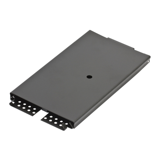
Align the hole in the cover with the hole in the tray. Snap the cover onto the tray (Figure 12).
10.
Splicing Single Fibers
NOTE: Place the tray as close to the splicing equipment as possible. This reduces the possibility of broken fibers
while transferring them from the tray to the splicer.
Step 1:
Route all fibers into the tray as described in Section 5. Make the largest circles possible to avoid
attenuation from tight bends. Make sure the fiber is under the inside lip of the tray.
Step 2:
Remove just enough fiber from the tray to reach the splicing equipment. Do not remove the entire
length of fiber from the tray or twist fibers as they are removed.
IMPORTANT:
When using heat-shrink splice protection (OSE-ST-1), slide the splice protector onto the fiber before
the fiber is spliced. When splicing into OSE-ST-2 splice trays, proceed to Section 11.
TPA-4953
Standard Recommended Procedure 001-285 | Issue 4 | February 2017 | Page 6 of 8
Figure 12
