CORNING EDGE8-04U Installation und Prüfung - Seite 12
Blättern Sie online oder laden Sie pdf Installation und Prüfung für Kontrolleinheit CORNING EDGE8-04U herunter. CORNING EDGE8-04U 13 Seiten. Tap module
Auch für CORNING EDGE8-04U: Installation und Prüfung (8 seiten)
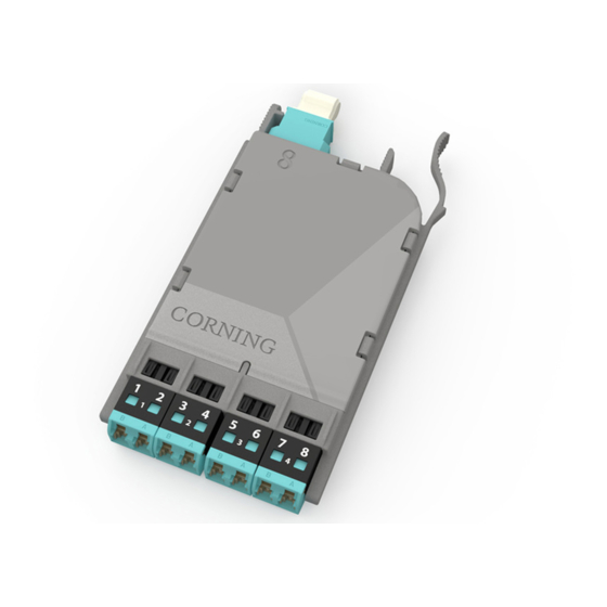
10. Simultaneous Testing of the Live and Tap Portions of an MTP
Tap Module
10.1
This section describes how to test the entire system at once with one source and two meters.
This is an alternative way to test compared to Steps 8 and 9. Note that this can only be done if all the
permanent harnesses are installed or test harnesses are purchased to mimic the harnesses that will be
installed. Also, three craft persons will be needed instead of two.
10.2
To calculate the system losses for the system use the values calculated above in Steps 8 and 9
and reference the test equipment as shown in Step 7.
10.3
To begin testing the system (Figure 16):
Step 1:
Install the Light Source/RJ1 LC connector into the number 2 port of the EDGE8
module, Module "B".
Step 2:
Install Meter 1/RJ2's LC connector adapter onto LC number 1 of the harness
plugged into the front-mounted LIVE Port of the MTP Tap module.
Step 3:
Install Meter 2/RJ3's LC connector adapter onto LC number 2 of the harness
plugged into the TAP port of the MTP Tap module.
Step 4:
Continue testing through on the even fibers of the EDGE8 module, Module "B," using
Tables 3 and 5 for testing sequences.
LC #1
"A"
RJ2
and
adapter
LC #8
Do NOT
disconnect
0.00 dB
M1
LC #2
RJ3
and
LC #8
adapter
Do NOT
disconnect
0.00 dB
M2
HPA-1006-EDGE8
STANDARD RECOMMENDED PROCEDURE 003-139-AEN | ISSUE 1 | JANUARy 2017 | PAGE 12 OF 13
Module harness
EDGE8 MTP Tap Module "A"
TAP port
test harness
"Near end"
Note: Fiber loss
depends on length
EDGE8 Module "B"
of system
multimode only
Do NOT
disconnect
RJ1
Light
Source
"Far end"
Figure 16