Gardena 1197 Betriebsanleitung - Seite 3
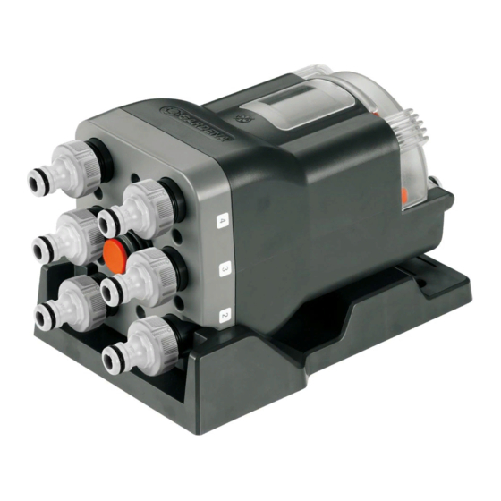
Blättern Sie online oder laden Sie pdf Betriebsanleitung für Water Pump Gardena 1197 herunter. Gardena 1197 12 Seiten. Water distributor automatic
Auch für Gardena 1197: Betriebsanleitung (12 seiten), Betriebsanleitung (12 seiten)

2. Safety instructions
The Water Distributor automatic may be
positioned at a maximum of 1.5 m lower than
the highest connected accessory.
The minimum water pressure for secure switch-
ing operation during irrigation is 1 bar.
If too many devices are connected to one line,
the pressure may fall below 1 bar and will be
insufficient for proper operation. To increase
water pressure, we recommend the GARDENA
Tap Connector Art. 2801 / 2817 with ³⁄₄ " hoses
on the inlet side.
Due to the switch mechanism of the Water
Distributor, there may be drop formation during
further switching at the outlets.
Please note : on completed irrigation, the
higher-lying connecting device empties over
the lowest-placed device.
For water containing sand, a pre-filter must be
used.
3. Assembly
Assemble mounting plate :
z
R
2
4. Initial Operation
Connect Water Distributor :
6
5 4 3
With the mounting plate
mounted on the ground or on a wall (inlet on top).
1. Using the mounting plate
4 holes.
2. Screw the mounting plate tight with 4 screws
1
Lock Water Distributor :
v From above, move the Water Distributor on the mounting
1
plate
until it locks into place.
Unlock the Water Distributor :
v Press the release button
wards.
Inlet side :
1. Remove the rubber seal
replace with the filter
2. Screw the Tap Connector
6
side
and connect with a hose to the Water Computer or
water tap.
The Water Distributor should not be connected
to Pressure Tank Units as these present too
large pressure fluctuations.
Functioning is only guaranteed with Original
GARDENA accessories.
The individual outlets can only be operated
one after the other.
For secure switching function of the Water
Distributor, the minimum water discharge
quantity is 20 l / h. E.g. for control of the
Micro-Drip System, a minimum of 10 two-
litre Drip Heads is required.
The Micro-Drip Master Unit may not be installed
on the inlet side of the Water Distributor.
Danger !
Small parts could be swallowed during
assembly and there is a risk of suffocation
from the polybag. Keep infants away during
assembly.
1
, the Water Distributor can be
1
, mark the drill holes and drill the
z
and pull the Water Distributor up-
R
4
from the Tap Connector
5
.
3
onto the connection on the inlet
2
(not included).
3
and
11
