Garmin G600 Anleitung Handbuch - Seite 5
Blättern Sie online oder laden Sie pdf Anleitung Handbuch für Avionik-Display Garmin G600 herunter. Garmin G600 14 Seiten.

2.2 Description of Alteration
The Garmin G500/G600 PFD/MFD System is a combination of Garmin LRUs designed to provide both a
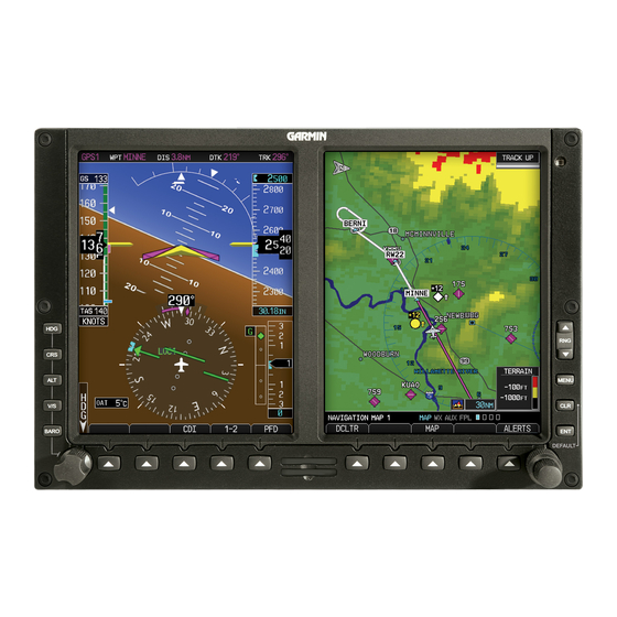
PFD and MFD in the primary field of view. The system consists of a GDU 620 display, GRS 77 AHRS,
GDC 74( ) ADC, GMU 44 magnetometer, and GTP 59 outside air temperature probe. This modification
may also include a Garmin GAD 43/43e Adapter and/or Mid-Continent Instruments attitude indicator
(models 4300-4( ), or 4200-( ) with MD420). Installation of the Garmin G500/G600 system, specific for
the aircraft installation, is documented in the G500/G600 AML STC Installation Manual.
2.3 Control, Operating Information
The GDU 620, GRS 77, GMU 44, and GDC 74( ) are powered by an electrical bus which is normally
energized with battery, generator, or external power applied to the aircraft. The GAD 43/43e is typically
powered by an avionics bus which is normally controlled by the avionics bus power switch. The LRUs
do not have individual power switches and are powered when the bus is energized and the circuit
breakers are closed. The following circuit breakers provide power to the individual LRUs:
• PFD: GDU 620
• AHRS: GRS 77 #1 and GMU 44 #1
• ADC: GDC 74( )
• GAD: GAD 43/43e
In a dual G500/G600 installation, the PFD, AHRS, and ADC circuit breakers are suffixed with the
numbers 1 and 2 (i.e. PFD 1 and PFD 2). If an LRU is optionally powered from multiple circuit breakers,
then the circuit breakers will be suffixed with the letters A and B (i.e. PFD 1A and PFD 1B).
The GDU 620 has a PFD and MFD display and front panel controls for performing all G500/G600 normal
and configuration operations. Knobs at the lower left and right corners are used for selecting and
entering data on each screen. The function of the soft keys along the bottom of the display is depicted
by the text above the key. There are dedicated ENT, CLR, and MENU keys on the MFD side of the unit.
Turning the PFD knob adjusts the values for the mode selected by the PFD bezel keys, such as,
Heading (HDG), Course (CRS), Altitude (ALT), Vertical Speed (V/S), and Barometric Setting (BARO).
The values are shown in a window to the left of the HSI. Pressing the PFD knob reverts to the default
value of the selected mode.
The Small (Inner) MFD Knob selects a specific page within a page group. Pressing the small MFD knob
turns the selection cursor ON and OFF. When the cursor is ON, data may be entered in the applicable
window by turning the small and large MFD knobs. In this case, the large MFD knob moves the cursor
on the page and the small MFD knob selects individual characters or values for the highlighted cursor
location. The Large (Outer) MFD Knob selects the MFD page group. When the cursor is ON, the large
MFD knob moves the cursor to highlight available fields.
The G500/G600 system starts in normal mode when power is applied to the LRUs. After completing the
self-test, the database confirmation page is displayed. Invalid or expired databases are displayed in
yellow. Press ENT to proceed to normal mode. Normal mode consists of a Primary Flight Display (PFD)
on one screen and a Multifunction Display (MFD) on the other screen. The AHRS alignment should
complete within one minute and attitude should be displayed on the PFD. System alerts are accessible
via an "ALERTS" softkey at the lower right of the MFD. During normal system operation with all aircraft
systems and avionics powered there should not be any red Xs or system alerts on the GDU 620.
To enter into Configuration Mode for the G500/G600 system, verify that the GDU 620 is off and an
Installer Unlock Card is inserted in the SD card slot of the GDU 620. Apply power to the GDU 620 while
holding the ENT key. Release the ENT key when "INITIALIZING SYSTEM" appears in the upper left
corner of the display.
Refer to the G500/G600 AML STC Installation Manual for further configuration instructions.
G500/G600 PFD/MFD System
190-00601-00 Rev. L
Instructions for Continued Airworthiness
Page 5 of 14
