Garmin gWind Einbauanleitung - Seite 2
Blättern Sie online oder laden Sie pdf Einbauanleitung für Schiffsausrüstung Garmin gWind herunter. Garmin gWind 4 Seiten. Provides wireless wind speed and wind angle information
Auch für Garmin gWind: Installationsanleitung Handbuch (46 seiten)

• If there is not a horizontal surface on the mast head, an
appropriate shim must be added to create a horizontal
surface.
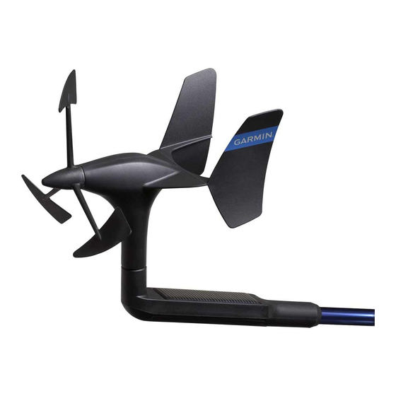
• The wind transducer should be installed facing the front of
the boat
, parallel to the center line.
NOTE: If you do not mount the device facing the exact front
of the boat, or mount it facing the back of the boat, you must
configure the wind-angle offset to receive accurate wind-
angle data by following the directions in these installation
instructions.
When selecting a mounting location for the wireless server
interface (WSI), observe these considerations.
• Before permanently mounting the WSI, you must test the
signal strength between the wind transducer and the WSI.
• The WSI is not water resistant and must be installed in a
location that is not exposed to any spray, washdown, or
submersion.
• The best location for the WSI is under the deck, near the
hull, as high as possible in the boat.
• You should install the WSI as close to the wind transducer as
possible.
• Metallic objects in the path of the wind transducer and the
WSI greatly reduce the transmission distance.
• The antenna is on the top of the WSI
when it is pointing toward the wind transducer.
• The WSI works the best when installed on a bulkhead
parallel to the pole of the wind transducer, in a fore-aft
direction.
Installing the Mounting Bracket
1
Using the mounting bracket as a template, mark the pilot
hole locations.
11
2
Using a 4.5 mm (
/
in.) bit, drill the pilot holes.
64
3
Securing the Device in the Mounting Bracket
1
2
3
4
Mounting the WSI
Before permanently mounting the WSI, you must test the signal
strength between the sensor and the receiving box.
1
2
3
4
Connection Considerations
The WSI must connect to a Garmin GND 10 to communicate
with the NMEA 2000 network on your boat. When connecting
, and works best
the included cable to the WSI and to the GND 10, observe
these considerations.
Item Description
Fasten the mounting bracket to the surface using the
included screws.
Loosen the lock nut
on the device by turning it counter-
clockwise by hand until it stops.
Place the device in the mounting bracket by pushing it down
and sliding it back until it stops
Secure the device in the bracket by turning the lock nut
clockwise by hand until it stops.
Attach the security clamp
nut from loosening.
Determine the mounting location.
Using the device as a template, mark the pilot hole locations
on the mounting surface.
1
Using a
/
in. drill bit, drill the pilot holes.
8
Use the included screws to attach the device to the mounting
surface.
These terminals are not used when connecting this device to a
GND 10 because the WSI is powered by the GND 10. If you
want to use the WSI with other Nexus
device owner's manual.
This connector fits only one way. Match the wire colors to the
terminal blocks before inserting the connector.
This connects to either NEXUS port on the GND 10
.
to the device to prevent the lock
®
products, see the Nexus
3
