Garmin GTX 320A Installationshandbuch - Seite 7
Blättern Sie online oder laden Sie pdf Installationshandbuch für Marine Radio Garmin GTX 320A herunter. Garmin GTX 320A 43 Seiten. Garmin gtx 320/320a transponder installation manual
Auch für Garmin GTX 320A: Handbuch für Piloten (4 seiten), Handbuch für Piloten (8 seiten), Installationshandbuch (37 seiten)

1
GENERAL DESCRIPTION
1.1
Introduction
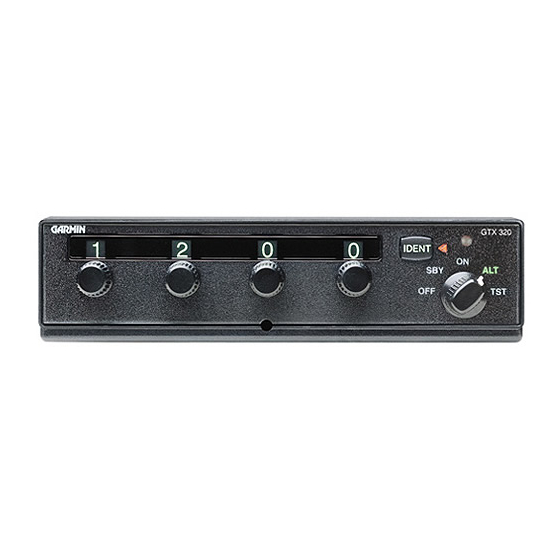
This manual provides the installation and operating instructions for the Garmin GTX 320 and the GTX 320A
Transponders. Information pertaining to the maintenance, alignment, and procurement of replacement parts is
found in the GTX 320 Maintenance Manual, P/N 190-00133-02 and the GTX 320A Maintenance Manual, P/N
190-00133-08. After installation of the GTX 320/ GTX 320A, FAA Form 337 must be completed by an
appropriately certificated agency and ATC transponder tests required by 14 CFR, Part 91.413 must be completed
to return the aircraft to service.
1.2
Equipment Description
The Garmin GTX 320/320A Transponder is a radio transmitter and receiver that operates on radar frequencies.
Receiving ground radar interrogations at 1030 MHz, it transmits a coded response of pulses to ground-based radar
on a frequency of 1090 MHz.
As with other Mode A/Mode C transponders, the GTX 320/320A replies with any one of 4,096 codes, which
differ in the position and number of pulses transmitted. By "replying" to ground transmissions, your
GTX 320/320A enables ATC computers to display aircraft identification, altitude and ground speed on ATC radar
screens. The GTX 320/320A is equipped with IDENT capability that activates the Special Position Identification
Pulse (SPI) for approximately 20 seconds (18 seconds for the GTX 320A) identifying your transponder return
from other aircraft on the controller's scope.
1.3
Technical Specifications
1.3.1
Transponder Specifications
TSO C74c Class 1A, JSTO C74C Class 1A
(A1D1)-CA(BMN)XXXXXXZBABAUZXXXXXX
GTX 320: FAA TSO C74c; RTCA DO-160C, JTSO C74c
GTX 320A: FAA TSO C74c; RTCA DO-160D, JTSO C74c
-20 C to +55 C (Continuous Operation)
GTX 320: 14/28 VDC: 12 Watts Max.
GTX 320A: 14/28 VDC: 20 Watts Max.
95% @ +55 C for 16 Hours; 85% @ +38 C for 32 Hours
50,000 Feet
1090 MHz
125 Watts minimum, 150 Watts nominal at the antenna with
1.5 dB coaxial cable loss at 1090 MHz
1030 MHz
GTX 320: -72 dBm Nominal for 90% replies
GTX 320A: -74 dBm Nominal for 90% replies
4096 Identification Codes
100 Foot Increments from -1000 to 63,000 Feet
Low
0.5 V; High
GTX 320/320A Installation Manual
190-00133-01
Table 1-1 Transponder Specifications
Characteristic
8 V
Specification
TSO, JTSO
TSO ENV CAT
Applicable Documents
Temperature Range
Power Requirements
Humidity
Altitude
Transmitter Frequency
Transmitter Power
Receiver Frequency
Receiver Sensitivity
Mode A Capability
Mode C Capability
External Suppression Input
Page 1-1
Rev M
