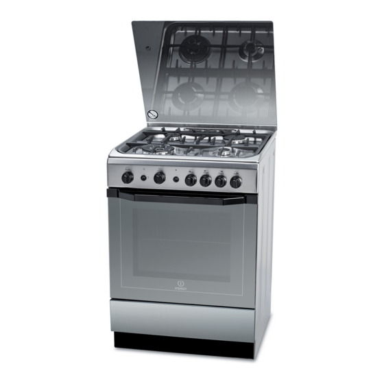
Indesit I6TG1G /EX Betriebsanleitung - Seite 5
Blättern Sie online oder laden Sie pdf Betriebsanleitung für Backofen Indesit I6TG1G /EX herunter. Indesit I6TG1G /EX 16 Seiten.

HOOD
600
Min.
mm.
blinds behind the cooker or less than 200 mm away
from its sides.
• Any hoods must be installed according to the
instructions listed in the relevant operating manual.
Levelling
If it is necessary to level the
appliance, screw the adjustable
feet into the places provided on
each corner of the base of the
cooker (see figure).
The legs* fit into the slots on the
underside of the base of the
cooker.
Electrical connection
Install a standardised plug corresponding to the load
indicated on the appliance data plate (see Technical
data table).
The appliance must be directly connected to the mains
using an omnipolar circuit-breaker with a minimum contact
opening of 3 mm installed between the appliance and the
mains. The circuit-breaker must be suitable for the charge
indicated and must comply with current national legislation
(the earthing wire must not be interrupted by the circuit-
breaker). The supply cable must be positioned so that it
does not come into contact with temperatures higher than
50°C at any point.
Before connecting the appliance to the power supply,
make sure that:
• The appliance is earthed and the plug is compliant with
the law.
• The socket can withstand the maximum power of the
appliance, which is indicated by the data plate.
* Only available in certain models
•
Do not position
• The voltage is in the range between the values
indicated on the data plate.
• The socket is compatible with the plug of the
appliance. If the socket is incompatible with the
plug, ask an authorised technician to replace it. Do
not use extension cords or multiple sockets.
! Once the appliance has been installed, the power
supply cable and the electrical socket must be easily
accessible.
! The cable must not be bent or compressed.
! The cable must be checked regularly and replaced
by authorised technicians only.
! The manufacturer declines any liability should
these safety measures not be observed.
IF THE FITTED PLUG IS REMOVED*
The flexible mains lead must be correctly connected as
below to a three pin plug of not less than 13 amp capacity.
If a B.S. 1363 fused plug is used, it must be fitted with a
fuse which is approved to B.S. 1362.
Important: the wires in the mains lead are coloured in
accordance with the following code:
Green & Yellow - Earth
- Neutral
Blue
- Live
Brown
The power supply cable must be type H05VV-F
Blue to
Neutral
Cord
Clamp
As the colours of the wires in the mains lead may not
correspond with the coloured markings identifying the
terminals in your plug, proceed as follows:
Connect the Green & Yellow wire to terminal marked "E"
or coloured Green or Green & Yellow.
or
Connect the Brown wire to the terminal marked "L" or
coloured Red.
Connect the Blue wire to the terminal marked "N" or
coloured Black.
FAILURE TO OBSERVE THE ACCIDENT-PREVENTION
REGULATIONS RELIEVES THE MANUFACTURER OF
ALL LIABILITY.
GB
Green &
Yellow to
Earth
Brown
to Live
3 Amp
Fuse
5
