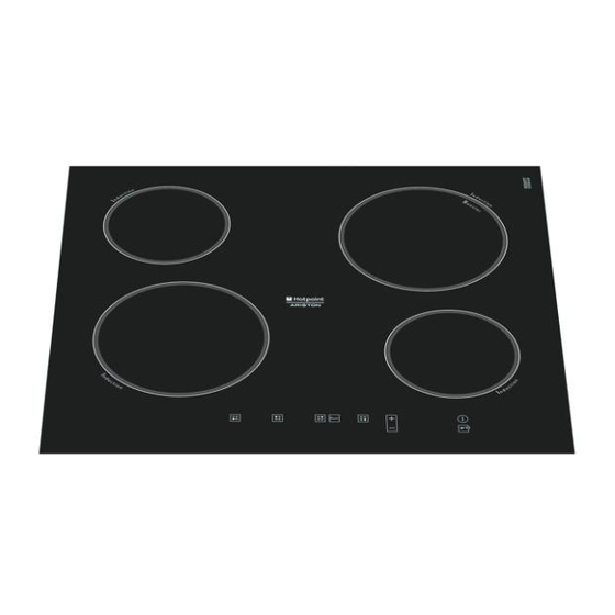
Indesit TIP 642 DD L Service-Handbuch - Seite 13
Blättern Sie online oder laden Sie pdf Service-Handbuch für Kochfeld Indesit TIP 642 DD L herunter. Indesit TIP 642 DD L 19 Seiten.

4.3: FAULT TABLE:
FAULT
SUBCODE
F01
1
F01
2
F02
1
F03
1
F03
2
F03
3
F04
1
F05
1
F05
2
F05
3
F06
1
F06
2
Service Manual
Induction hob manual
DESCRIPTION
Visual board NTC SC
Visual board NTC OC
Comunication VISUAL <--> cookeye/
clipsoeye MODULE
Keyboard not operative (all the but-
tons except for ON/OFF button)
Keyboard: ON/OFF button not ope-
rative
Communication VISUAL <--> TOUCH
Too high temperature of Visual
Board
ISI UART 1 (CN 03): hob NTC SC,
Large induction hotplate
ISI UART 1 (CN 03): hob NTC OC,
Large induction hotplate
ISI UART 1 (CN 03): Large induction
hotplate not connected
ISI UART 1 (CN 03): hob NTC SC, small
induction hotplate
ISI UART 1 (CN 03): hob NTC OC,
small induction hotplate
CHECK ACTIONS
•
Replace the Display board
•
Replace the Display board
Fault Not available
•
1. Check the correct installation of the Touch-Visual communication Flat
2. Clean Flat contacts and reconnect them
3. Wait 3 minutes without energizing the hotplates. If F03 is signalled
again, replace the display board.
4. If no fault is notifi ed after 3 minutes, energize the hotplates and wait
for 3 minutes. If F03 is signalled, replace the Display Board. If it is
not signalled, it is OK
1. Check the correct installation of the Touch-Visual communication
Flat
2. Clean Flat contacts and reconnect them
3. Wait 3 minutes without energizing the hotplates. If F03 is signalled
again, replace the display board.
4. If no fault is notifi ed after 3 minutes, energize the hotplates and wait
for 3 minutes. If F03 is signalled, replace the Display Board. If it is
not signalled, it is OK
1. Check the insulation of Display board housing
2. Check Display board NTC calibration (only in Dr.)
3. Replace the Display board
1. Check the inductor, verifying that the contacts are well connected
and clean.
2. Check NTC ohmic values (it must not be SC or OC)
3. Replace the inductor if NTC is out of calibration
4. Replace the power board.
NOTE: notifi ed on the corresponding inductor.
1. Check the inductor, verifying that the contacts are well connected
and clean.
2. Check NTC ohmic values (it must not be SC or OC)
3. Replace the inductor if NTC is out of calibration
4. Replace the power board.
NOTE: notifi ed on the corresponding inductor.
1. Check the inductor, verifying that the contacts are well connected
and clean.
2. Check NTC ohmic values (it must not be SC or OC)
3. Replace the inductor if NTC is out of calibration
4. Replace the power board.
NOTE: notifi ed on the corresponding inductor.
1. Check the inductor, verifying that the contacts are well connected
and clean.
2. Check NTC ohmic values (it must not be SC or OC)
3. Replace the inductor if NTC is out of calibration
4. Replace the power board.
NOTE: notifi ed on the corresponding inductor.
1. Check the inductor, verifying that the contacts are well connected
and clean.
2. Check NTC ohmic values (it must not be SC or OC)
3. Replace the inductor if NTC is out of calibration
4. Replace the power board.
NOTE: notifi ed on the corresponding inductor.
Edition
2008.03.01
13
Language
English
