A.H. Systems AK-571-4 Betriebshandbuch - Seite 11
Blättern Sie online oder laden Sie pdf Betriebshandbuch für Antenna A.H. Systems AK-571-4 herunter. A.H. Systems AK-571-4 14 Seiten. Horn antenna kit

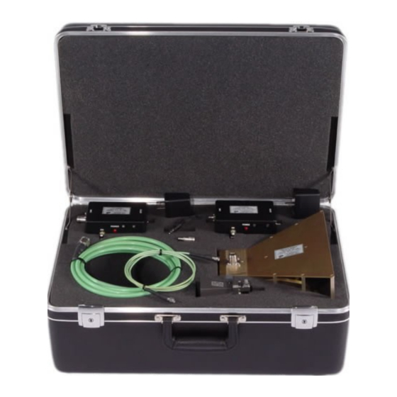
A.H. Systems AK-571-4 Horn Antenna Kit
ANTENNA FORMULAS AND CALCULATIONS
EMISSIONS TESTING
Individual calibration data for the log periodic antenna is supplied at appropriate
distances (3, and 10 meter) to comply with various emissions test requirements.
For emissions measurements, add antenna factor plus cable loss to receiver
reading in dBV to convert to field strength in dBV/meter.
Field Strength(dBuV/m) = SA(dBuV) + AF(dB/m) + cable loss (dB)
IMMUNITY TESTING
For Immunity measurements, the generated electric field strength can be
calculated by:
The constant in the above equation is derived as follows. Power is related to voltage according to
Ohm's law. The Log
Note, the resistance of 50 used above reflects that RF systems are matched to 50
systems use decibels referenced from 1 mW, the corresponding voltage increase for every 1 mW
The logarythmic form of Ohm's law shown above is provided to describe why the log of the
A.H. Systems inc. – Apr 2020
REV C
SA = Spectrum Analyzer or Receiver voltage reading
AF = Antenna Correction Factor
CL = Cable Loss in dB
FS = Approximate Field Strength in (V/m)
P = Power in watts
g = Numeric Gain
d = Distance in meters
Common RF Related Conversion Factors
function is used for relative (dB) scales, so applying the logarythm function to
10
Ohm's law, simplifying, and scaling by ten (for significant figures) yields:
10Log
power increase can be calculated with another form of Ohm's law.
V = (PR)
Given a resistance of 50and a power of 1 mW
20Log
corresponding voltage is multiplied by 20.
dBmW = dBV - 107
P = V
/ R
2
[P] = 20Log
[V] - 10Log
10
10
= 0.223 V = 223000 V
0.5
[223000 V] = 107 dB
10
[50
]
10
. Since RF
11
