DeZurik APCO CVS-250A Gebrauchsanweisung - Seite 7
Blättern Sie online oder laden Sie pdf Gebrauchsanweisung für Kontrolleinheit DeZurik APCO CVS-250A herunter. DeZurik APCO CVS-250A 16 Seiten. Swing check valves

Maintenance
(Continued)
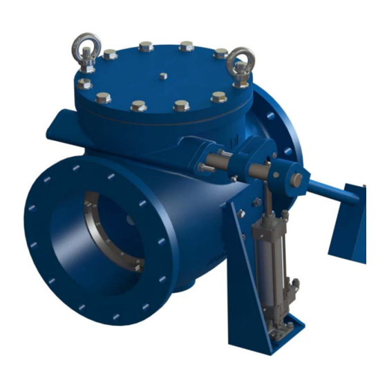
Changing Counterweight or Spring Assembly to Opposite Side of Valve
These valves may open or close, swinging the counterweight/spring loaded arm without
warning due to flow changes from pumps starting and stopping. Servicing or working
around these valves while the pipeline is under pressure can cause personal injury or
equipment damage.
Workers must be cautious when working around these valves. Relieve pipeline pressure
and lockout the pumps before servicing the valve.
1. Relieve the pressure in the pipeline and close the valve. Lockout the pumps.
2. Loosen the Screw (B55) and remove the Counter Weight Arm (B19) and Weight (B29)
assembly or Spring (B59) with Spring Bracket (B60). (Note that a special spring bracket may be
required to change lever & spring assembly to opposite side of valve.)
3. If the valve is equipped with an Air Cylinder (B20):
a. Remove the Retaining Rings (B60) and Clevis Pin (B59) from the cylinder rod eye.
b. Remove the Cushion Cylinder (B20) and Bracket (B24) assembly from the Body (A01).
c. Remove the Cushion Lever (B27) from the Pivot Shaft (A13).
4. Remove the Packing Gland (A37), Packing (A17) and Studs (A49) from the Body (A01).
5. Remove the Screws (A16) and Pivot Shaft Cover (A15) from the Body (A01)
6. Remove the Eye Nuts (A64), Nuts (A52), Screws (A04), Washers (A51) and Cover (A02) from
the Body (A01).
7. Loosen the Screws (A14) in the Disc Arm (A09).
8. Insert a threaded bolt (1/4-20) into the Pivot Shaft Retaining Pin (A60) and remove the pin from
the pin hole in the top of the Body (A01).
9. Remove the Pivot Shaft (A13) from the Body (A01). The Packing (A17), Flanged Bushing (A12,
on 4" and larger valves) and the Pivot Shaft Disc Key (A33) will be removed along with the
shaft.
10. Remove the Straight Bushing (A11), on 4" and larger valves from the Body (A01) and install it
on the opposite side of the body aligning it with the pin hole in the top of the body.
11. Align the Disc Arm (A09) with the holes in the Body (A01) for the Pivot Shaft (A13); insert the
pivot shaft with the Pivot Shaft Disc Key (A33) with the groove and shorter keyway end first into
the opposite side of the body, through the disc arm and align the pivot shaft retaining groove
with the pin hole in the body.
12. Insert the Pivot Shaft Retaining Pin (A60) thru the hole in the top of the Body (A01) so the pin
goes thru the Straight Bushing (A11), on 4" and larger valves in into the groove in the Pivot
Shaft (A13). The pin should be flush with the top of the body.
13. Center the Disc (A10) assembly and the Body Seat (A05).
14. Tighten the Screws (A14) in the Disc Arm (A09).
October 2018
APCO CVS-250/250A Swing Check Valves
Page 7
DeZURIK
D12003
