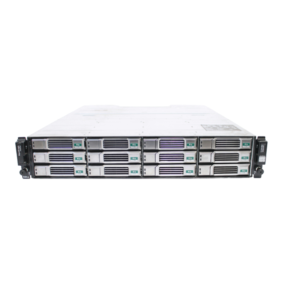
Dell PS4100 Hardware-Wartungshandbuch - Seite 25
Blättern Sie online oder laden Sie pdf Hardware-Wartungshandbuch für Server Dell PS4100 herunter. Dell PS4100 47 Seiten. Storage array
Auch für Dell PS4100: Hardware-Handbuch (50 seiten), Übersicht (7 seiten), Handbuch für Installation und Einrichtung (41 seiten), Einrichten (2 seiten)

PS4100 Hardware Maintenance Guide
Table 5 Ethernet and Management Port LED Descriptions
LED Location
State
Left
Off
On
Right
Off
On
Table 6 Control Module Status LED Descriptions
LED Name
State
PWR
Off
On (steady green) Power/OK.
ACT
Off
Steady green
Steady amber
ERR
Off
Steady red
Blinking red
Identifying Control Module Failures
You can identify a failure in a control module by:
• LEDs on the control module itself. See
• Messages on the console, in the event log, or in the Group Manager GUI Alarms panel.
• Group Manager GUI and CLI output. The Member Controllers window or the
command output shows the control module status
controllers
When viewed from the rear of the array, CM0 is on the top, and CM1 is on the bottom. See
Features and Indicators on page
replacement.
Understanding Failover Behavior
In a dual control module array, only one control module is active (serving network traffic) at one time. Each
control module includes a cache-to-flash module for storing recently-used data.
For redundancy, the cache on the secondary control module mirrors the data that is stored in the cache on
the active control module.
The active control module can use network interfaces on the secondary control module if there is a cable
connected from the corresponding port on the secondary control module to a network switch. Therefore, you
should connect cables to all the network interface ports on each control module to make sure that both
control modules can access an interface.
Description
No power or not connected to network.
Connected to network.
No power, not transmitting, or not receiving.
Transmitting or receiving.
Description
No power.
No power, secondary control module is not synchronized with
active control module, or error condition.
Active control module (serving network I/O).
Secondary control module. Cache is synchronized with active
control module.
Normal operation or no power.
Array is starting up or error condition.
Array is entering power standby mode because the Standby On/
Off button was pressed.
Interpreting Control Module LEDs on page
3. If a control module fails, contact your PS Series support provider for a
Maintaining Control Modules
18.
member select show
.
not installed
Front-Panel
19
