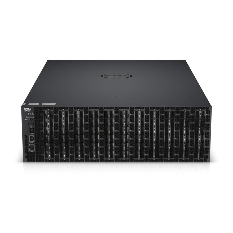
Dell Networking Z9500 Installationshandbuch - Seite 12
Blättern Sie online oder laden Sie pdf Installationshandbuch für Schalter Dell Networking Z9500 herunter. Dell Networking Z9500 47 Seiten. Z9500 switch
Auch für Dell Networking Z9500: Handbuch "Erste Schritte (34 seiten)

Utility Panel
The Utility panel side of the platform contains the fan and power modules.
Figure 2. Utility Side
1.
Fan Trays
Power Supplies
The Z9500 supports four hot-swappable Power supply units (PSUs) .
NOTE: The PSUs must be installed at the customer site.
PSUs are field replaceable. To ensure power redundancy and adequate cooling, install four power
supplies in the switch. When running with full redundancy (four PSUs installed and running), you can
remove and replace a PSU while the other PSUs are running without disrupting traffic.
Fans
The Z9500 supports five fan trays with airflow directions from I/O to Utility.
The fans must be installed at the customer site.
System Status
You can view Z9500 status information in several ways, including:
•
LEDs
•
CLI show commands
•
Simple network management protocol (SNMP)
For more information about these options, refer to the Dell Networking Command Line Reference Guide
and Dell Networking Configuration Guide for the Z9500 Switch.
As shown in the following figure, the Z9500 includes LED displays on the I/O and Utility side of the
chassis. When the Z9500 powers up or reloads, the status LED on the power supplies are solid green.
The following table lists the LED definitions for the Z9500 system.
12
2.
Power Supplies
Hardware Overview
