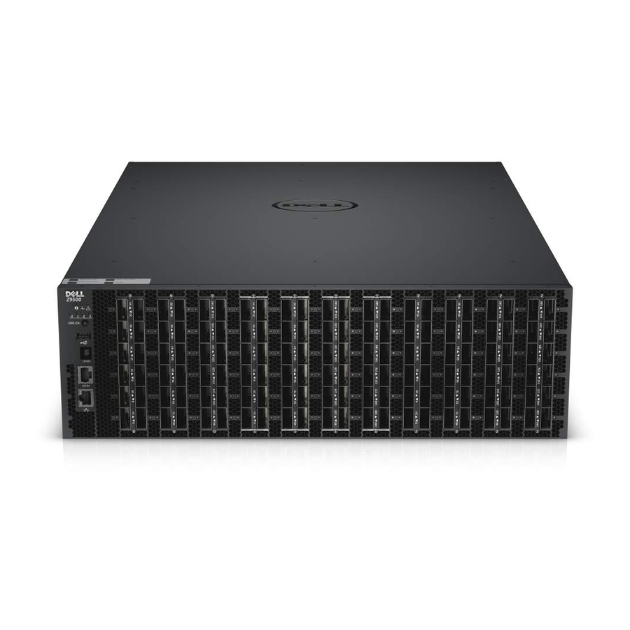
Dell Networking Z9500 Installationshandbuch - Seite 28
Blättern Sie online oder laden Sie pdf Installationshandbuch für Schalter Dell Networking Z9500 herunter. Dell Networking Z9500 47 Seiten. Z9500 switch
Auch für Dell Networking Z9500: Handbuch "Erste Schritte (34 seiten)

Installing Fan Modules
The chassis requires five fan modules to be installed for normal configuration. The airflow direction must
be from I/O to Utility.
Important Points to Remember for Installing a Fan Module
•
The Utility panel consists of five slots numbered from 0 to 4. Insert the fan modules in slots 0, 1, 2, 3,
and 4.
•
If a fan module fails, the system during normal operation continues to operate without a significant
degradation in cooling capacity for a TBD duration.
•
The cooling system is designed such that, during normal operation, the fans typically run at
somewhere between 40 and 50 percent of their maximum speed at 26°C ambient temperature. This
feature results in lower noise and higher average fan life. The switch increases the fan speed to
maximum if the facility air condition fails or if a fan fails.
•
The fan speed increases and decreases automatically based on the internal temperature. The switch
never intentionally turns off the fans.
•
For proper ventilation, position the switch in an equipment rack (or cabinet) with a minimum of 5
inches (12.7 cm) of clearance around the exhaust vents. When you install two systems near each
other, position the two chassis at least 5 inches (12.7 cm) apart to permit proper airflow. The
acceptable ambient temperature ranges are listed in
•
To view the log messages, use the show logging command. For more information, refer to the
System Logs chapters of the Dell Networking OS Command Line Reference Guide for the Z9500
Switch and Dell Networking OS Configuration Guide for the Z9500 Switch.
28
Technical
Specifications.
Z9500 Installation
