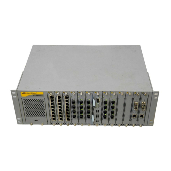
Allied Telesis AT-8400 Series Installationshandbuch - Seite 2
Blättern Sie online oder laden Sie pdf Installationshandbuch für Stromversorgung Allied Telesis AT-8400 Series herunter. Allied Telesis AT-8400 Series 2 Seiten. Line card and power supply
blank faceplate
Auch für Allied Telesis AT-8400 Series: Installationshandbuch (2 seiten)

Package Contents
Make sure the following items are included in your package. If any of these
items are missing or damaged, contact your Allied Telesyn sales
representative.
AT-8403 Fan
Two Phillips-head screws
Installation Guide
Replacing the AT-8403 Fan
You can replace the AT-8403 Fan in either the Fan A or Fan B slot at the rear
of the AT-8400 Chassis. You do not have to power down the chassis to replace
the fan.
Use the following procedure to replace the AT-8403 Fan.
Remove rings and watches before replacing fans.
WARNING:
To avoid electric shock, do not place fingers or hands inside fan slot
WARNING:
1.
Remove the fan from the rear of the chassis using a Phillips-head
screwdriver, as shown below.
B
4 0 3
2
.
P W R
B
F A N
A
P W R
A
A T - 8
4 0 3
2.
Insert the new fan into the Fan A or Fan B slot at the rear of the chassis,
as shown below. Check that the AT-8403 part number is right-side up.
B
4 0 3
A T - 8
4 0 3
3.
Fasten the two Phillips-head screws on the top of the fan as shown below.
You have completed the fan installation procedure.
B
4 0 3
P W R
B
F A N
A
P W R
A
P W R
B
F A N
A
P W R
A
A T - 8
4 0 3
3
