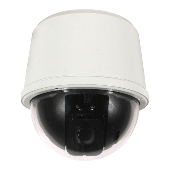
360 Vision Visiondome-VR Handbuch zur Installation und Konfiguration - Seite 5
Blättern Sie online oder laden Sie pdf Handbuch zur Installation und Konfiguration für Sicherheitskamera 360 Vision Visiondome-VR herunter. 360 Vision Visiondome-VR 16 Seiten.

Visiondome VR Installation Manual Ver 2.7
4 Connections
To ensure optimum Visiondome VR performance these parameters must be adhered to. Failure to do so will
invalidate the warranty.
Wall and Swan Neck mount options are supplied with 7m power, RS485 data and coax cables. These are fitted
using cables glands.
Please note that the External Vandal Dome is water sealed to its bracket. The Dome is supplied with
connection cables which can be cut down to any required length.
Please note that if the customer seperates the Dome from its bracket this will damage the waterproof
seals and will therefor invalidate the 3 year warranty.
Cable Size
Maximum Distances
0.75mm²
1.00mm²
1.25mm²
1.50mm²
2.00mm²
Coax Video Connection board
Power Connections
Connect 24Vac/30vdc to CON2.
Data Connections
Connect RS485 (D+/D-) to Dome connection board using CON3.
Video Connections
Connect Video Coax cable (Video/Gnd) to Dome connection board
using CON4.
RS485 Data
Data +
Data -
Power
V + (AC)
V - (AC)
Video
Video Signal
Video Ground
© 360 Vision Technology Ltd.
VisionDome VR
(Using VRVD-PSU)
30 metres
40 metres
50 metres
60 metres
100 metres
Blue
Yellow
Brown
Blue
Centre Core
Coax Shield
Page 5
