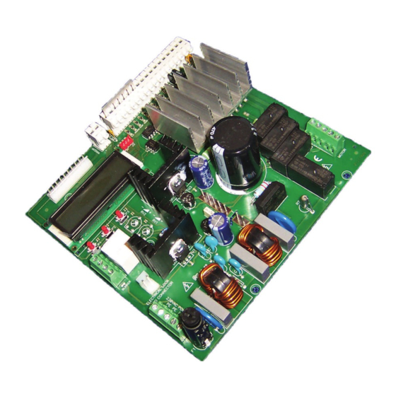
Allmatic CT INVERTER AM Handbuch für die Installation - Seite 2
Blättern Sie online oder laden Sie pdf Handbuch für die Installation für Kontrolleinheit Allmatic CT INVERTER AM herunter. Allmatic CT INVERTER AM 12 Seiten. Programmable control board for sliding gates with inverter technology

1. Introduction
The Single-phase control unit CT INVERTER AM is a device suitable for operating and controlling the sliding gate in a way easy and complete; it is
designed in order to satisfy all possible needs.
The inverter on board allows to set the maximum torque limits along with the possibility to modify the frequency (the speed of the motor).
The possibility to use motors with encoder allows the unit to detect possible obstacles along the run and reverse its direction of motion. It is suitable to
command and control automatics accesses with its single-phase motor 230Vac max 1,5KW (current limited to 10A) WITHOUT using a starting
condenser. Every control board is equipped with a memory module that stores all personal settings and parameters needed for operating the control
board (these data can be transferred from one unit to another one). It is equipped with inputs for self-tested photocells, keys for SS (step-by-step),
PED (partial opening), OPEN and CLOSE, switch limits, security stops and a wide display with 3 keys for settings. It is also equipped with a molex
connector for a plug-in receiver, output for courtesy and flashing light. It is possible to connect an additional card (R1) to operate an electric lock.
WARNING: DO NOT INSTALL THE CONTROL UNIT WITHOUT READING THE INSTRUCTIONS FIRST!
For the connection of the motor we recommend to use a screened cables 3 poles + earth 1.5 mm
For the connection of the possible encoder we recommend to use a screened cable 3 x 0,75mm
NOTE: All unused NC inputs must be jumpered with the common.
In case an encoder is applied, it is compulsory to use a shielded cable with the screening connected to the EARTH
6-1622595
rev.06
13/01/2017
It is FUNDAMENTAL to connect the motor and the unit
to the EARTH in order to operate the control unit correctly!
only by one end of the cable itself.
ITA
ENG
2
(type FD781CY)
2
(type OLFLEX-110CH)
FRA
ESP
DEU
POR
ANTENNA
Antenna
COM
Common
S.S.
Step by Step
PHOTO
Photocell
STOP
Stop
EDGE
Safety edge
L.S.CL.
Closing limit switch
L.S.OP.
Opening limit switch
PED.
Partial opening
OPEN
Opening command
CLOSE
Closing command
ENCODER
Encoder
SIG.
Encoder signal
GND
Ground
PHOTO POWER
Photocells power
SUPPLY
supply
+RX
Photo Receiver
+TX
Photo transmitter
CLOSE (21)
OPEN (22)
Motor connections
COM
(23)
PE
Earth
N
Neutral
Power supply
L
Phase
SYSTEM MEMORY
System memory
BLINKER
Flashing light
COURTESY LIGHT
Courtesy light
ELECTRIC LOCK
Electric lock or brake
CARD CONNECTOR
card connector
RADIO RECEIVER
Radio receiver
FUSE
Fuse
INPUT LEDS
Input leds
POWER ON LEDS
Power on leds
2 / 12
