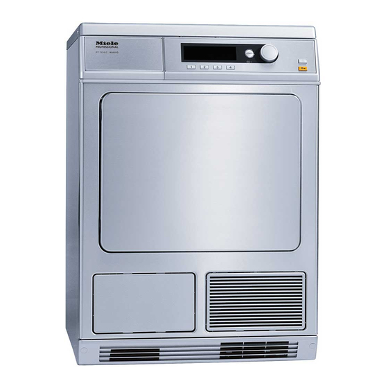
Miele PT 5135 C EL Installationsplan - Seite 9
Blättern Sie online oder laden Sie pdf Installationsplan für Trockner Miele PT 5135 C EL herunter. Miele PT 5135 C EL 10 Seiten. Condenser tumble dryer
Auch für Miele PT 5135 C EL: Betriebs- und Installationsanleitung (48 seiten), Betriebs- und Installationsanleitung (48 seiten), Installationsplan (13 seiten)

j S
N
W
J
Cold air intake
Cold air
discharge vent
Condensate drain
hose
Fittings (supplied)
Installationsplan PT 7135 C / PT 5135 C EL
Stand: 31.05.2005
3. Standard voltage (as supplied)
Frequency
Rated load
Fuse rating
Connection cable, min. cross-section
Length of supply lead (H05 RN-F without plug)
(supplied)
4. Standard voltage (as supplied)
Frequency
Rated load
Fuse rating
Connection cable, min. cross-section
Length of supply lead (H05 RN-F without plug)
(supplied)
5. Standard voltage (as supplied)
Frequency
Rated load
Fuse rating
Connection cable, min. cross-section
Length of supply lead (H05 RN-F with plug)
(supplied)
6. Standard voltage (as supplied)
Frequency
Rated load
Fuse rating
Connection cable, min. cross-section
Length of supply lead (H05 RN-F with plug)
(supplied)
Plug and socket connection in accordance with IEC 60309
recommended to facilitate electrical safety tests.
Install mains isolator according to IEC 60947 on hard-wired
connection.
Wall socket or mains isolator must be accessible after
installation.
The use of an earth leakage circuit breaker (ELCB) is strongly
recommended.
If necessary, equipotential bonding with good galvanic contact
must be provided in accordance with all appropriate national
and local regulations.
Unobstructed vent required for cold air
Unobstructed vent required for cold air
Max. temperature
Drain hose (Int. dia. × wall thickness × l) [DN 10]
Hose sleeve for drain hose to be provided on site (ext. dia. x l) mm
Max. transient throughput
Max. head height (measured from base of unit)
Miele plinth UG/UO 5005
4 × metal angled brackets (to secure machine to plinth)
4 × screws DIN 571 (Ø × length)
4 × rawl plugs (Ø × length)
Machine must be bolted to the floor!
Fixing materials for floating screed floor to be provided on site
On concrete platform
2 × screws DIN 571 (Ø × length)
2 × rawl plugs (Ø × length)
Machine must be bolted to the floor!
Fixing materials for floating screed floor to be provided on site
V
2N AC 400
Hz
50
kW
3.68
A
2 × 10
mm²
4 × 1.5
mm
2000
V
1N AC 230
Hz
50
kW
3.68
A
1 × 16
mm²
3 × 1.5
mm
2000
V
1N AC 230-240
Hz
50
kW
2.15 – 2.35
A
1 × 10
mm²
3 × 1.0
mm
2000
V
2N AC 200
Hz
50-60
kW
2.85
A
2 × 20
mm²
3 × 2.75
mm
2000
°C
60
mm
10 × 2.5 × 2000
10 × 30
l/min
3
mm
1000
mm
8 × 65
mm
12 × 60
mm
6 × 50
mm
8 × 40
Seite 9
