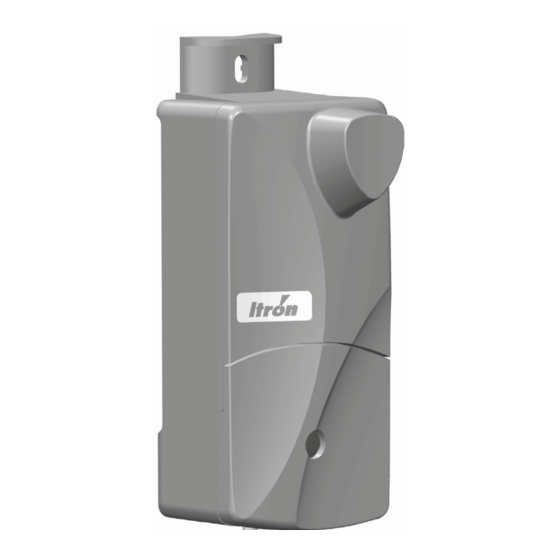
Allmess ITRON EquaScan pMIURF Montage- und Programmieranleitung - Seite 6
Blättern Sie online oder laden Sie pdf Montage- und Programmieranleitung für Kontrolleinheit Allmess ITRON EquaScan pMIURF herunter. Allmess ITRON EquaScan pMIURF 8 Seiten. Pulse meter radio module

Radio specifications
Protocol
Operating mode
Frequency Band
Electromagnetic compatibility
Limitation of human exposure to
electromagnetic fields
Information technology safety
INSTALLING THE EQUASCAN pMIU
Equipment required: screwdriver, pliers.
The EquaScan pMIU
can be:
RF
- Screwed on the wall
- Fixed with tie-ups on a pipe
• First, the radio module shall be configurated. Please follow the programming steps described below.
• The distance between 2 EquaScan pMIU
• The cable length for the Meter connection to the EquaScan pMIU
• A fitting extension cable with 1m length can be ordered under the following order-no.: 17799
• Connect the signal wires of the EquaScan pMIU
There is no need to strip the signal wires.
• Close the cover with the metallic screw.
• Place the blue user plastic seal on the screw.
To initially start the EquaScan pMIU
Cyble Sensor (3wires/5wires) is attached, this connection is ensured by the Cyble Sensor.
PROGRAMMING
To ensure the correct data transmission between the pulse emitting meter and
the EquaScan pMIU
, the meter parameter must be defined and programmed
RF
into the module. To do this, the EquaScan software is used. Each EquaScan
pMIU
has an inductive interface, over which the module is configured. Informa-
RF
tion on the index and device can be read and recorded over at any time, inde-
pendently of the radio operation. The inductive interface serves to quickly and
accurately parameterize and read data via the computer using an inductive head
(Order No.8090000006). See picture for positioning the inductive head.
READING AND PROGRAMMING THE MODULE
After the EquaScan pMIU
RF
module parameters becomes available. The activated programming parameters can be selected and overwritten with new
values. These changes are adopted in the module when the next writing process begins. Other module values and param-
eters can be read from the various selection fields.
WARNING
The responsibility, in case of deviation between the mechanical index and the electronic index of the EquaScan pMIU
cannot be attributed to Itron. We invite the users to check carefully the connection between the module and the EquaScan
pMIU
. We strongly recommend to proceed with the configuration of the EquaScan pMIU
RF
emitting meter. We strongly recommend the installation of non-return valve or breaks to avoid the risk of reverse flow.
EN 13757-3/-4 wireless M-BUS
C2 Mode
Tx: 868,95 MHz / Rx: 869,525 MHz
Interference Immunity: ETSI EN 301 489-1-V1.9.2 (2011-09)
Emitted Frequency :
RF
must be 20 cm minimum.
RF
RF
the wires GND(black or brown) and TAMP(green) have to be connected. If an Itron
RF
has been read via the inductive interface, the entry form for the EquaScan pulse meter RF
ETSI EN 301 489-3-V1.6.1
ETSI EN 301 489-17-V2.2.1
EN 61000-3-2 (2006+A1 / 2009+A2 / 2009)
EN 61000-3-3 (2008)
ETSI EN 300 220-1 (V2.4.1)
ETSI EN 300 220-2 (V2.4.1)
EN 62311 (2008)
EN 60950-1:2006+A11:2009+A1:2010+A12:2011+A2:2013
shall be not exceed 10m.
RF
to the pulse emitter with the « scotch-lock » type connectors.
before connecting the pulse
RF
,
RF
