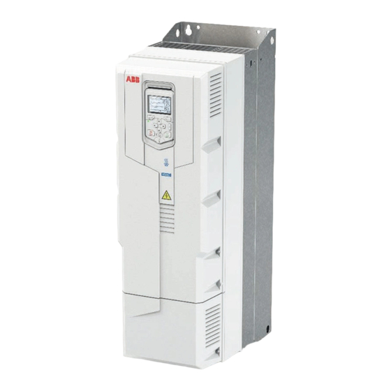
ABB ACH580-31 Kurzanleitung für Installation und Inbetriebnahme - Seite 5
Blättern Sie online oder laden Sie pdf Kurzanleitung für Installation und Inbetriebnahme für Industrielle Ausrüstung ABB ACH580-31 herunter. ABB ACH580-31 16 Seiten. Converter modules with electrolytic dc capacitors in the dc link
Auch für ABB ACH580-31: Handbuch (16 seiten)

Connection procedure with VFD cable
For connection procedure with conduits, see
1.
Attach a residual voltage warning sticker in the local language.
2.
Frames R6 and R8: Remove the shroud on the power cable terminals.
Frame R8: For easier installation, you can remove the side plates.
R6
R6
3.
Prepare the power cables:
•
Remove the rubber grommets of the cables to be installed from the cable entry plate. Remove the unused grommets
and reinstall with the cone pointing down (3a).
•
Cut a sufficient hole in the rubber grommet. Slide the grommet onto the cable (3b) with the remaining cone pointing
down.
•
Prepare the ends of the input power cable and motor cable as illustrated in the applicable figure (3c).
•
Slide the cables through the holes in the cable entry and attach the grommets to the holes.
3a
4.
Connect the power cables. For the tightening torques, refer to
•
Ground the shield 360 degrees by tightening the clamp of the power cable grounding shelf onto the stripped part of
the cable (4a).
•
Connect the twisted shield of the cable shields to the grounding terminals (4b).
•
Frame R8: to install the common mode filter, see
•
Connect the phase conductors of the motor cable to the T1/U, T2/V and T3/W terminals. Connect the phase
conductors of the input power cable to the L1, L2 and L3 terminals (4c).
•
Tighten the screws to the torque given in the installation drawing below.
R3
1.7 N·m
L1, L2, L3, T1/U, T2/V, T3/W: 1.7 N·m (15 lbf·in)
Connection procedure with conduit
PE
3c
3b
Related documents
1.7 N·m
4a
1.7 N·m
(15 lbf·in)
.
R8
R8
Terminal
data.
.
4c
4b
R8
PE
1.7 N·m
5
