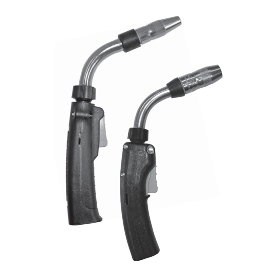
Miller Bernand PipeWorx MIG Gun Betriebshandbuch - Seite 13
Blättern Sie online oder laden Sie pdf Betriebshandbuch für Zubehör für das Schweißen Miller Bernand PipeWorx MIG Gun herunter. Miller Bernand PipeWorx MIG Gun 21 Seiten.

Part IV Maintenance and Repair
See pages 6 and 7 for parts lists
Disconnect gun from equipment, allow to cool, and remove
electrode from liner before servicing.
Contact Tip
Gas Diffuser
Section 1. Nozzle
A. Removal
Threaded fit nozzle can be removed by turning in a counter-
clockwise direction.
B. Service
Inspect nozzle for cracks and degradation of insulation.
Clean the nozzle as often as possible to prevent spatter
build-up which can lead to poor gas shielding or short cir-
cuiting. Replace the nozzle when loose, worn, or producing
erratic gas shield.
C. Installation
Replace threaded fit nozzle by threading in a clockwise direc-
tion. Nozzle body is used to secure contact tip.
Section 2. Contact Tip
Bernard has designed Centerfire™ Contact Tips to allow rapid installa-
tion and adjustment.
A. Removal
Cut electrode and remove all burrs. Remove threaded fit
nozzle by turning in a counterclockwise direction. Pull the
Centerfire Contact Tip from gas diffuser.
FIGURE #1
Nozzle
Section 3. Gas Diffuser
Section 4. Neck
B. Service
To extend contact tip life, reface front of contact tip and
clean the bore. Contact tips may be rotated in gas diffuser/
head socket providing additional wear surface and extending
the service life of the product.
C. Installation
Replacement is accomplished by cutting electrode and
removing all burrs. Slide contact tip over electrode into gas
diffuser and replace threaded fit nozzle by threading in a
clockwise direction. Nozzle body is used to secure contact
tip.
A. Removal
The head may be removed with an appropriate wrench in a
counterclockwise rotation.
B. Service
Inspect head for spatter, blocked gas ports, and carburized
surfaces. Clean as often as possible. Replace with new gas
diffuser when wear prevents engagement of contact tip or
nozzle.
C. Installation
Firmly secure gas diffuser with an appropriate wrench in a
clockwise rotation, torque to 144 in-lbs. Be sure insulator
cap is in place as shown in figure #1.
A. Removal
Grasp lock nut and rotate counterclockwise, rotation will free
neck from end fitting.
B. Installation
Before installing, inspect neck and end fitting for debris,
clean if necessary. Install neck in reverse order, torque to 38
in-lbs. NOTE: Refer to Jump Liner literature for liner cut off
sizes (if used).
13
