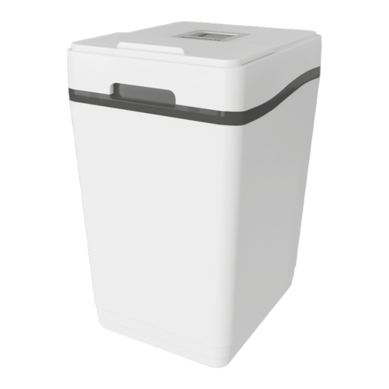
AQUAPHOR S800 Betriebshandbuch - Seite 10
Blättern Sie online oder laden Sie pdf Betriebshandbuch für Wasserspender AQUAPHOR S800 herunter. AQUAPHOR S800 20 Seiten.

Figure 3
Well water
Shut-o valve
Municipal water
Electrical
outlet
Air gap
(5 cm minimum)
Drain and
overflow lines
NOTE: Teflon tape or sealant must not be used when
connecting with flexible hoses. When connecting with
other supply fittings, use only Teflon tape to seal the
connections.
• Check that the direction of water flow is correct using
the arrow on the bypass valve (see section "Bypass
valve").
ATTENTION! Do not connect the softener to the water
supply in the opposite direction! This can lead to sof-
tener failure.
• Tighten the flexible hose nuts. Do not apply excessive
force so as not to damage the threaded part of the
fittings.
Figure 4
In
PM
10
Hard water for garden
and other needs
In
Figure 5
Out
PPM
Ground wire and clamps
(only for copper pipes)
Out
ATTENTION! To ensure the possibility of dismantling
the filter, it is recommended to use a bypass circuit
from standard components (fig. 5).
Step 3. Connect the overflow line
• The overflow line is designed to drain excess water
when the brine tank is overfilled or the softener de-
pressurizes.
• Screw the elbow overflow fitting included with the
softener into the hole on the back of the softener
housing and point downwards (see fig. 6).
• Install a flexible tube with an inner diameter 12 mm
(1/2") (smaller tubing is not permitted) between an
overflow fitting and a drain, washing machine drain,
Service position
(the appliance is on)
Water supply is o
On
Cold "soft" water
Hot "soft" water
Water heater
Bypass position
(the appliance is o )
Water supply is o
On
O
