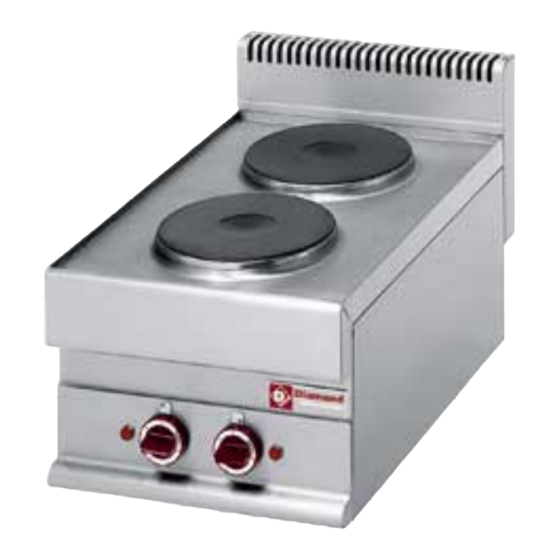
Diamond 65/40 PCE Installation - Use - Maintenance - Seite 8
Blättern Sie online oder laden Sie pdf Installation - Use - Maintenance für Ranges Diamond 65/40 PCE herunter. Diamond 65/40 PCE 19 Seiten. Range, gas solid top
Auch für Diamond 65/40 PCE: Installation & Wartung (19 seiten)

REPLACING THE NOZZLE AND THE MAIN BURNER
PRIMARY AIR REGULATION
Remove the control panel.
Remove nozzle UM and replace it with the one
indicated in table TAB1.
Retighten nozzle UM.
Slacken screw V and position the air regulator at
distance A as indicated in table TAB1.
Retighten screw V fully.
Reassemble all parts. For assembly, proceed in
reverse order.
REPLACING THE MINIMUM ADJUSTMENT SCREW
Remove the control panel.
Remove nozzle UM and replace it with the one
indicated in table TAB1.
Retighten nozzle UM.
Reassemble all parts. For assembly, proceed in
reverse order.
REPLACING THE PILOT BURNER NOZZLE
Remove the control panel and internal guards.
Undo connector R.
Remove nozzle UP and replace it with the one
indicated in table TAB1.
Retighten connector R. Reassemble all parts.
Following, in reverse order, the sequence used for
their removal.
GAS OVEN
REPLACING THE NOZZLE AND THE MAIN BURNER
PRIMARY AIR REGULATION
Open the oven door.
remove the sole and the protection panel
Slacken screw V.
remove the UM nozzle.
Retighten nozzle UM.
Place the aeration adjuster at the distance A
specified in the table TAB1.
Retighten screw V fully.
Reassemble all parts. For assembly, proceed in
reverse order.
REPLACING THE MINIMUM ADJUSTMENT SCREW
Remove the control panel.
Remove nozzle UM and replace it with the one
indicated in table TAB1.
Retighten nozzle UM.
Reassemble all parts. For assembly, proceed in
reverse order.
GAS STOCKPOT STOVE
REPLACING THE NOZZLE AND THE MAIN BURNER
PRIMARY AIR REGULATION
Remove the control panel.
Remove nozzle UM and replace it with the one
indicated in table TAB1.
Retighten nozzle UM.
Slacken screw V and position the air regulator at
distance A as indicated in table TAB1.
Retighten screw V fully.
Reassemble all parts. For assembly, proceed in
reverse order.
REPLACING THE MINIMUM ADJUSTMENT SCREW
Remove the control panel.
Remove nozzle UM and replace it with the one
indicated in table TAB1.
Retighten nozzle UM.
Reassemble all parts. For assembly, proceed in
reverse order.
REPLACING THE PILOT BURNER NOZZLE
Remove the control panel.
Undo connector R.
Remove nozzle UP and replace it with the one
indicated in table TAB1.
Retighten connector R. Reassemble all parts.
Following, in reverse order, the sequence used for
their removal.
9. COMMISSIONING
Following installation, conversion to a different
type of gas or any maintenance operations, check
appliance operation. In the event of any
malfunction, consult the next Paragraph "
Troubleshooting " .
GAS APPLIANCES
Switch on the appliance as directed in the
instructions and reminders for use given in
10
