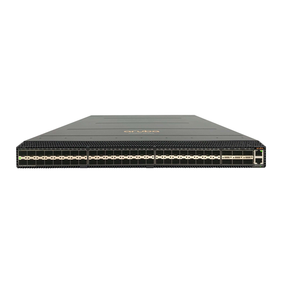
HP R8P13A Anweisungen für die Demontage - Seite 2
Blättern Sie online oder laden Sie pdf Anweisungen für die Demontage für Schalter HP R8P13A herunter. HP R8P13A 4 Seiten.

Item Description
Components and parts containing toner and ink,
including liquids, semi-liquids (gel/paste) and toner
Components and waste containing asbestos
Components, parts and materials containing
refractory ceramic fibers
Components, parts and materials containing
radioactive substances
2.0 Tools Required
List the type and size of the tools that would typically be used to disassemble the product to a point where components
and materials requiring selective treatment can be removed.
Tool Description
Torx Screwdriver
Phillips Screwdriver
3.0 Product Disassembly Process
3.1 List the basic steps that should typically be followed to remove components and materials requiring selective treatment:
1.
Unscrew 7x T10 screws for top cover
2.
Slide top cover backward from the faceplate to open the cover
3.
Unscrew 17x screws securing Main PCBA and Console PCBA
4.
Unscrew 2x screws securing Trident3 heatsink
5.
Remove Console PCBA from motherboard
6.
Slide PCBA away from faceplate and lift back of PCBA to disassemble from chassis
7.
Disassemble all plastic baffles from PCBA
8.
Disassemble all heatsinks from motherboard
3.2 Optional Graphic. If the disassembly process is complex, insert a graphic illustration below to identify the items
contained in the product that require selective treatment (with descriptions and arrows identifying locations).
Attachment 1: System PCA
Attachment 2: Location of Coincell.
MF877-00
Template Revision C, 30-July-2018
Copyright 2018 Hewlett Packard Enterprise Development LP
HPE instructions for this template are available at
Notes
Include the cartridges, print heads, tubes, vent
chambers, and service stations.
Tool Size (if
applicable)
T10
#1
MF877-01
Quantity
of items
included
in product
0
0
0
0
Page 2
