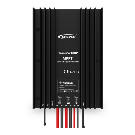
Epever Tracer5210BP Handbuch
Blättern Sie online oder laden Sie pdf Handbuch für Controller Epever Tracer5210BP herunter. Epever Tracer5210BP 2 Seiten. Mppt solar charge controller
Auch für Epever Tracer5210BP: Handbuch (2 seiten), Schnellstart-Handbuch (2 seiten)

※Thank you for selecting the Tracer BP series MPPT solar charge
controller. Please read this manual carefully before using the
product and pay attention to the safety information.
Tracer BP series
---
1.Safety Information
Read all of the instructions in the manual before installation.
DONOT disassemble or attempt to repair the controller.
Install external fuse or breaker as required.
Do disconnect the solar module and fuse/ breakers near to battery before installing
or moving the controller.
Power connections must remain tight to avoid excessive heating from a loose
connection.
Only charge batteries that comply with the parameters of controller.
Battery connection may be wired to one battery or a bank of batteries.
Risk of electric shock, the PV and load can produce high voltages when the
controller is working.
2. Overview
The Tracer BP series solar charge controller adopt to the advanced Maximum Power
Point Tracking charging methods, it enables the system charging and discharging
management to obtain the most radical optimization. Increase the system flexibility, yet
lower down the system cost. The controller support a variety of battery, for example
sealed, gel, flooded and lithium battery. User can view and modify the working status
and parameters. It can be widely used on solar home system, traffic signal, solar street
light, solar garden lamp, etc. The features are listed below:
Adopt high quality components of ST,IR and Infineon, make sure product using
lifespan
Wide working environment temperature
Apply to lead-acid battery and lithium battery
Lithium battery self-activating and low temperature protection function
Maximum conversion efficiency of 98%
Advanced Maximum Power Point Tracking (MPPT) technology, with tracking
efficiency no less than 99%
Ultra-fast tracking speed and guaranteed tracking efficiency
Accurately recognizing and tracking of multiple power points
PV power limitation function
Monitoring and setting parameter via Mobile APP, PC Monitor setting software with
RS485 communication interface.
Use of standard Modbus communication protocol for RS485 bus connections,
communication protocol compatibility much better
Connecting the IOT(Internet of Things) module and Cloud Server monitoring software
to realize remote monitoring of the multi-machine system
The RS485 connector can provide power supply
Aluminum housing for better cooling
Real-time energy statistics function
IP67 waterproof degree
3. Product Features
⑴
①
Temperature Sensor
②
PV Positive and Negative Wires
③
Battery Positive and Negative Wires
④
Load Positive and Negative Wires
⑴The temperature sensor short-circuited or damaged, the controller will be
charging or discharging at the default temperature 25 º C.
⑵The port can provide the DC power supply of 5VDC/150mA and have the short
circuit function.
NOTE: When the RS485 communication port is not working, the
waterproof cap must be installed to prevent water getting in.
4. Wiring
HUIZHOU EPEVER TECHNOLOGY CO., LTD.
MPPT Solar Charge Controller
⑤
Charging Status LED indicator
⑥
Battery Status LED indicator
⑦
RS485 waterproof port
⑧
Waterproof cap(Included)
1
Tel:+86-10-82894896 / 82894112/+86-752-3889706
Connection Order
1) Connect components to the charge controller in the sequence as shown above and
pay much attention to the "+" and "-".Please don't insert the fuse or turn on the breaker
during the installation. When disconnecting the system, the order will be reserved.
2) After power on the controller, check the battery LED indicator on the controller, it will
be green. If it's not green, please refer to chapter 10.
3) Connect a fuse in series through battery positive (+) in the circuit and the battery
circuit fuse must be 1.25 to 2 times to the rated current. The installed distance is within
150mm.
Load self-test function
The load is ON when the controller power on 10s. After 10s it will restore to set working
mode.
5. LED Indicators
Indicator
Charging(green) and battery
indicator(orange)flashing simultaneously
※When the battery type is Lithium Battery,the controller do not recognize the
system voltage automatically.
6.Load Working Mode
1) Manual Mode(Default ON)
2) Light ON/OFF
3) Light ON+ Timer
4) Real-time Control
⑵
Control the load ON/OFF time through setting real-time clock.
NOTE: In the mode of Light ON/OFF and Light ON/Timer, the Load is
turned on after 10Min. delay.
7. Accessories(optional) and Software
1)PC Software
www.epever.com ——Solar Station Monitor
2)APP Software
Android phone
www.epever.com——ChargeController(Li)
IPhone
APP Store——EPEVER——EP-01
Website:www.epever.com
Color
Status
PV connection normal
but low
Green
On Solid
voltage(irradiance)
from PV, no charging
No PV voltage(night
time) or PV connection
Green
OFF
problem
Green
Slowly Flashing(1Hz)
In charging
Green
Fast Flashing(4Hz)
PV Over voltage
Green
On Solid
Normal
Green
Slowly Flashing(1Hz)
Full
Green
Fast Flashing(4Hz)
Over voltage
Orange
On Solid
Under voltage
Red
On Solid
Over discharged
Battery Overheating
Red
Fast Flashing(4Hz)
Low temperature
System voltage error※
2
Instruction
