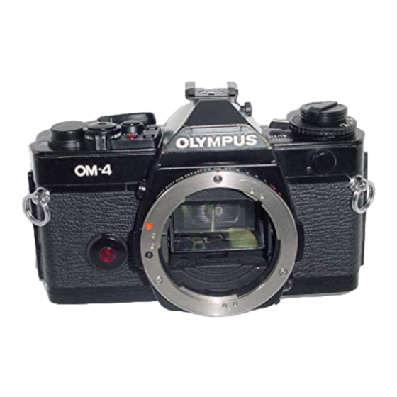
Olympus OM-4 Handbuch zur Fehlersuche - Seite 9
Blättern Sie online oder laden Sie pdf Handbuch zur Fehlersuche für Digitalkamera Olympus OM-4 herunter. Olympus OM-4 24 Seiten.

,ir-i03
This 1C lives beneath the mirror box floor and can only
be reached by removing the front plate. Its outputs are
BV (measured at pin 7, IC102) and integration
(measured at pin 3, IC-102). If these are correct, the 1C is
probably working. If not, you may want to remove the
front plate, then check connections according to the
drawing,
Pin 16 is the BV output measured at pin 7, IC102.
Typical voltage is l,5v to 1.7v, 18mv/LV.
Pin 10 is integration output measured at pin 3, IC-103.
See scope trace for "Auto" mode.
IC-104
This 1C lives under a circuit board between the prism and
ASA resistor. It is not easy to reach for tests, but
important inputs can be checked at ICs 101 and 102, Its
output, of course, is the LCD,
Pin 1 is CLK input, Check at pin 53,IC-I02 and the white
wire,
Pin 5 is Vcc in from IC-102. Check at pin 54, IC-102.
Pin 6 is B-,
Pin 11 is data sync signal from IC-101. Check scope trace
at pin 12, IC-101 and the green wire.
Pin 12 is serial data in. Check scope trace at pin I I ,
IC-101 and the yellow wire.
Pin 13 is data clock signal in. Check at pin 10, IC-101
and the blue wire.
If there is no display, check for proper connections to
pins 3 and 4 and from there to capacitor C-3Q2. This is the
6-volt power source for the LCD,
OLYMPUS OM-4, PAGE 9
