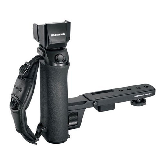
Olympus FP-1 Anleitung Handbuch - Seite 5
Blättern Sie online oder laden Sie pdf Anleitung Handbuch für Kamera-Zubehör Olympus FP-1 herunter. Olympus FP-1 20 Seiten. Flash power grip

Assembly
1.
Attach the grip and bracket.
1.
2.
3.
• Clamp the bracket firmly so that it does not rattle.
2.
Attach the electronic flash FL-50 (optional).
To avoid a malfunction, be sure to turn the FL-50 and flash
power grip off beforehand.
1.
• Store the removed protective cap in the storage position
2.
3.
3.
Attach the camera.
1.
• The camera can be attached to one of the four holes.
• The Power Battery Holder HLD-2 can also be attached.
20
Loosen the grip mount screw on the bracket.
Fit the bracket into the bracket mounting rail and slide the
bracket down.
Position the bracket as desired, then tighten the Grip mount
screw.
Remove the protective cap from the FL-50's external power
connector.
as shown in the figure on the left.
Slide the FL-50 into the flash power grip's hot shoe. Make
sure the FL-50 is connected firmly to the connection termi-
nals.
Turn the lock ring of the FL-50 all the way to [←LOCK].
Attach the camera by inserting the camera mount screw
into the tripod hole of the camera.
4.
Connect the bracket cable (optional).
Also read the bracket cable (optional) instruction manual.
If the camera has a hot shoe:
Connect the bracket cable FL-CB02 (optional) between
the flash power grip's bracket cable terminal and the
camera's hot shoe.
If the camera does not have a hot shoe:
Connect the bracket cable FL-CB01 (optional) between
the flash power grip's bracket cable terminal and the
camera's 5-pin external flash connection terminal.
5.
Attach the remote grip cable RG-1 (optional).
1.
Remove the caps from the remote grip cable terminals on
Rear view
the flash power grip and camera.
• To avoid losing the removed cap, attach it to the terminal
cap attaching position.
• The flash power grip has two remote grip cable terminals.
Select whichever is most convenient.
2.
When connecting the remote grip cable to the bracket on
the flash power grip, align the indented section of the cable
plug with the projecting part of the terminal, insert the plug
Terminal cap
attaching position
and turn the knob clockwise to tighten.
21
