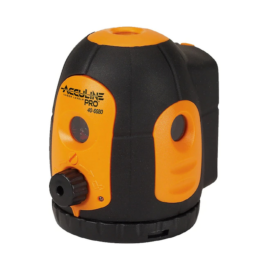
AccuLine 40-6680 Service-Handbuch - Seite 4
Blättern Sie online oder laden Sie pdf Service-Handbuch für Zubehör AccuLine 40-6680 herunter. AccuLine 40-6680 16 Seiten. 5 beam laser pointer
Auch für AccuLine 40-6680: Gebrauchsanweisung (13 seiten)

2.2 Core Module Disassembly (AP1827)
Item
JLT Part
Description
#
5-6-1
AP1832
Hair Spring Module 1
5-6-2
AP1475
M2 x 5 Cross Plate Screw
5-6-3
AP1833
Hair Spring Module 2
5-6-4
AP1834
M2 x 12 Cross Plate Screw
5-6-5
AP1835
Gimbal Module
5-6-6
AP1836
Compensator Module
5-6-7
AP1837
M3 x 4 Inner Hex Tightening
Screw
5-6-8
AP1838
M2 x 4 Cross Plate Screw
5-6-9
AP1839
Connecting Board
5-6-10
AP1491
M2 x 8 Cross Plate Screw
5-6-11
AP1840
Prism Modules
5-6-12
AP1491
M2 x 8 Cross Plate Screw
5-6-13
AP1841
Laser Module 1
5-6-14
AP1491
M2 x 8 Cross Plate Screw
5-6-15
AP1842
Laser Module 2
5-6-16
AP1843
ST2.2×6.5 Cross Self
Tapping Screw
5-6-17
AP1475
M2 x 5 Cross Plate Screw
5-6-18
AP1844
Support Bracket
1.
Using a soldering iron, de-solder one end of four hairsprings
between the hairspring board module 1 (5-6-1) and 2 (5-6-3).
2.
Using a Phillips screwdriver, remove 4 cross-slot plate
tapping screws ST2.2×6.5 (5-6-16), and remove hairspring
board module 1 (5-6-1).
3.
Using a Phillips screwdriver, remove 2 cross-slot plate
screws M2×5 (5-6-2), then remove hairspring board module
2 (5-6-3).
4.
Using a Phillips screwdriver, remove 4 cross-slot plate
screws M2×5 (5-6-17) and disassemble 2 brackets 2 (5-6-18).
Reference see figure 9.
Prepared By: Tim Wojo
5-6-16, 5-6-17, and 5-6-18 are not
shown. Reference figure 9 for detail
Qty
1
2
1
5- 6- 4
4
1
5- 6- 5
1
1
5- 6- 9
2
1
4
5- 6- 13
1
5- 6- 12
4
3
4
2
4
4
2
5- 6- 1
5- 6- 2
5- 6- 3
Revision - Date: 0 – 20080430
40-6680 Service Manual
5- 6- 11
5- 6- 10
5- 6- 6
5- 6- 1
5- 6- 2
5- 6- 3
5- 6- 8
5- 6- 14
5- 6- 15
5- 6- 7
5- 6- 16
5- 6- 17
5- 6- 18
Figure 9
Page 4 of 16
