ABB UC Benutzerhandbuch - Seite 10
Blättern Sie online oder laden Sie pdf Benutzerhandbuch für Industrielle Ausrüstung ABB UC herunter. ABB UC 12 Seiten. On-load tap-changers
1
7
8
9
10
11
12
13
14
15
16
17
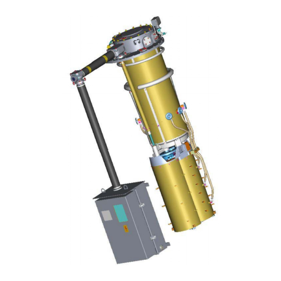
Layout of motor-drive mechanism, type BUL
1. Position indicator with draghands for max. and
min. position
2. Tap-change in progress indicator
(Red = in progress, White = in position)
3. Counter
4. Outgoing shaft with multihole coupling half
5. Shaft for handcrank
6. Lifting eye
7. Locking device prepared for padlock
8. (Option) Multi position switches
9. (Option) Measuring amplifier
10. (Option) Switch for extra heater
11. (Option) Outlet
10
2
3
4
18
19
20
5
6
21
22
23
12. (Option) Earth fault protector (when outlet is installed)
13. Emergency stop
14. RAISE/LOWER switch
15. LOCAL/REMOTE switch
16. Protective motor switch
17. Air vent
18. Door operated switch for lamp
19. Terminal blocks
20. Hand lamp
21. Heater 50 W + optional 100 W
22. (Option) Thermostat or hygrostat for extra heater 100 W
23. Descriptions and circuit diagram
24. Handcrank
24