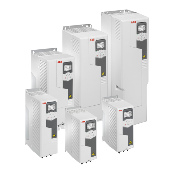
ABB ACS580-01 drives Kurzanleitung für Installation und Inbetriebnahme - Seite 11
Blättern Sie online oder laden Sie pdf Kurzanleitung für Installation und Inbetriebnahme für Controller ABB ACS580-01 drives herunter. ABB ACS580-01 drives 17 Seiten. Frequency converter. nec types
Auch für ABB ACS580-01 drives: Handbuch (16 seiten), Kurzanleitung für Installation und Inbetriebnahme (17 seiten)

4.
Select the localization you want to use and press
5.
To complete the first start assistant, select the values and settings
when prompted by the assistant. Continue until the panel shows that
the first start is complete.
When the panel shows that the first start is complete, the drive is ready
for use. Press
(Done) to enter the Home view.
6.
The Home view shows the values of the selected signals.
7.
Make additional adjustments, for example macro, ramps and limits,
starting from the Main menu. Press
enter the Main menu.
Select Primary settings and press
With the Primary settings menu, you can adjust settings related to the
motor, PID, fieldbus, advanced functions and clock, region and display.
You can also reset logs, parameters, and the control panel Home view.
ABB recommends that you make at least these additional settings:
• Choose a macro or set start, stop and reference values separately
• Ramps
• Limits.
To get more information on the Primary settings menu items, press
to open the help page.
Motor overload protection
The motor thermal overload protection is set to motor current and motor class curves as default. Motor thermal overload
protection can also be measured using motor temperature devices or can be estimated using a motor model defined by
parameters. To enable protection using motor model parameters or measurement devices set parameter
subsequent parameters through
35.57
.
?
Use the information key ( ) on the drive control panel for more information on setting group 35 parameters. You must set
the drive overload parameters correctly, or motor damage could occur.
Fieldbus communication
To configure the embedded fieldbus communication for Modbus RTU, you must set at least these parameters:
Parameter
20.01 Ext1 commands
22.11 Ext1 speed ref1
(Menu) in the Home view to
(Select) (or
35.55.
To adjust motor class curves (default is class 20), change parameters
Setting
Description
Embedded
Selects fieldbus as the source for the start and stop commands when
fieldbus
EXT1 is selected as the active control location.
EFB ref1
Selects a reference received through the embedded fieldbus interface
as speed reference 1. Use this parameter with the vector motor control
mode.
(Next).
).
?
11
35.11
and
35.56
and
