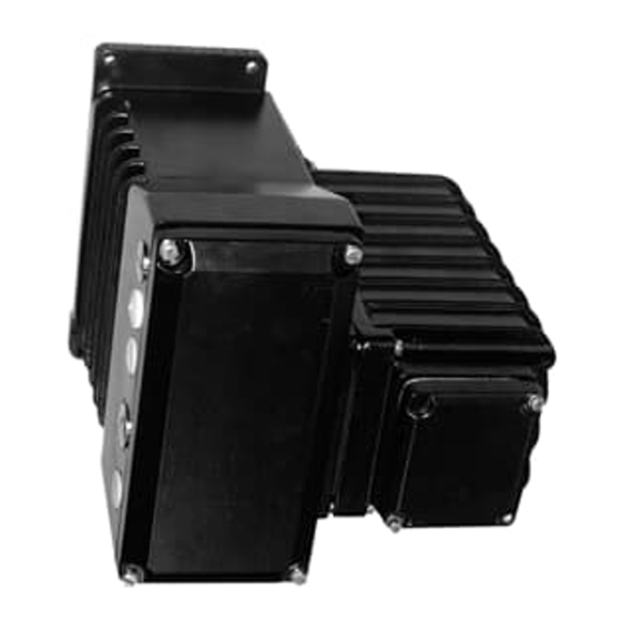
ABB EAN823 Anleitung Handbuch - Seite 10
Blättern Sie online oder laden Sie pdf Anleitung Handbuch für Controller ABB EAN823 herunter. ABB EAN823 17 Seiten. Power electronic units for field installation. for the control of contrac actuators of the pme, lme, rhd or rsd series

9.3
Connecting the cable shield
3
Fig. 10: Connecting the cable shield of EAN823; EBN853; EBN861
Screen connection at the actuator ist done accordingly.
9.4
Example for signal input / output
(conventional analogue / binary control)
Premises to switch the actuator into automatic mode (AUT):
- digital inputs D1, D2, and D3 may not be activated via the configuration software (standard config-
uration with default factory settings).
- activate the AUT mode using the configuration software (standard configuration with default factory
settings).
9.4.1
Standard wiring (analogue setpoint)
+ Y
1
2
+ -
Fig. 11: Possible wiring for standard terminal assignment
9.4.2
Behind a step controller
(binary control without an analogue setpoint)
Contrac actuators feature smooth and continous operation even if the elctronic unit receives binary
commands from a step controller. Use the configuration software for the appropriate settings. The elec-
tronic unit will then integrate the step commands and internally generate an analogue setpoint signal.
1
+ -
Fig. 12: Possible wiring for „operation behind step controller"
This operating mode requires the switch for the reference potential
10
1
2
4
AUT
MAN
- Y
5
3
4
6
7
8
9 10
+ -
+ -
+ Y
- Y
5
2
3
4
6
7
8
9 10
+ -
+ -
4
3
- Remove approximately 2 cm of the cable
sheathing (1) at the cable entry of the
housing (4).
- Open the cable shield in this area and fold
1
- Insert the cable end in the cable entry and
fasten it with the clamp; make sure that the
shield is folded back and in contact with
the clamp and the electronics housing.
r00331x1
26
27
11
12
13
14
15
+ -
-
+
RB
24V
+ -
11
12
13
14
15
+
-
24V
it back over the cable sheathing (1).
28
29
30
31
+
-
RB
+
I
+ -
Uv
U
24V
26
27
28
29
30
31
+ -
+
-
RB
RB
+
I
+ -
+ -
Uv
U
24V
SYS
to be set to
r00358x1
r00359x1
.
