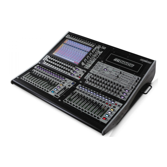
digico SD8 Sicherheitshinweise, Setup- und Installationshandbuch - Seite 9
Blättern Sie online oder laden Sie pdf Sicherheitshinweise, Setup- und Installationshandbuch für Musik Mixer digico SD8 herunter. digico SD8 13 Seiten. Replacing and cleaning faders
Auch für digico SD8: Handbuch (9 seiten)

User Option panels .......................................................................
The Upper section of the right hand worksurface incorporates a removable panel. A further, smaller, removable panel is fitted to the rear
of the mixer immediately behind the surface panel.
This is provided so that users can fit their own custom panel, or adapt the existing panel - this could be used for machine remotes, plasma
displays, Analogue meters etc.
Under no circumstances should mains voltages be connected to this panel. Such systems should be controlled remotely by low voltage
circuits (maximum 24V).
Note also that the interior of the mixer worksurface is electrically very noisy, and contains a variety of sensitive electronic circuits running
at very high clock-speeds.
Digico cannot be responsible for interference caused by the mixer to devices connected to the Accessory Panel, or for interference from
the panel affecting the operation of the console. The console should be commissioned and tested without this installed prior to testing user
external systems.
Interface Rack Units and Modules ...............................................
Audio signals are connected to the console via Rack Units. Each Rack Unit is a 19-inch chassis with a control panel at the bottom.
There are 3 available style of interface rack. MadiRack (standard for SD8) DigiRack and Mini rack.
The Madirack is 8U (310mm) high with a fixed 48 mic/line input format with slots for up to 3 output only Rack modules
The Digirack is 9U (353mm) high with 14 card slots, each of which can accept a Rack Module, up to 7 input and 7 output modules
The Minirack is 5U (220mm) high with a total of 4 cards slots with may be input or output or a mix of both.
Each Rack is a standard 19" wide, The units are 365mm deep, excluding connectors.
Rack Power Supply, Cooling .......................................................
Rack Units have twin supplies each with their own separate mains power connections, 2 IEC mains inputs per rack.
At least 1U (45mm) of space should be left above and below the rack unit to allow ventilation, and to prevent heat
transfer from adjacent equipment. At least 200m should allowed to side of the units to allow heat disippation.
At least 100mm / 4" should be left the connector side of the rack to allow ventilation. However this clearance is usually required to allow
connector access in any case.,
Rack Signal Earthing ....................................................................
The analogue earthing requirements of the Rack unit is similar to those of a conventional large analogue console. All analogue
inputs and outputs are balanced and symmetrical, but not floating, because of their transformerless design. Installers should use
good earthing practice, as with any large audio installation. Digico can provide copies of AES papers on this subject upon request.
Rack Control Panel Connections ................................................
The Rack Unit control panel provides connectors as follows:
MADI MAIN IN & OUT (2 x BNC)
MADI AUXILIARY IN & OUT (2 x BNC)
OPTOCORE® A IN & OUT (HMA Optical) (Option)
OPTOCORE® B IN & OUT (HMA Optical) (Option)
WORD SYNC IN & OUT (2 x BNC)
The MADI IN and OUT connections carry audio to/from the Worksurface. There are 2 sets, MAIN & AUXILIARY. The Coax and
Optical (where fitted) are effectively in parallel. MAIN & AUXILIARY are selected in software. Only 1 MADI connection can be
active at 1 time,
The Word Clock Out socket can be used to synchronise other digital devices in the system to the console.
The Word Clock In socket is only used to synchronise the rack system in special stand alone mode. It is NOT available to sync
the main system.
The LED indicator on the panel shows the condition of the Rack Unit's power supplies, whether the unit is synchronised and
information of the Rack Status via the 4 buttons and a simple menu system.
Input / Output Slots
Above the panel, the Rack Unit has Input and Output slots. Dependent on the rack version, each of these slots can be filled
with a different Rack Module, providing an I/O system which is configured according to model or user requirements.
Page 9
