ABB LME620-AN Anleitung Handbuch - Seite 6
Blättern Sie online oder laden Sie pdf Anleitung Handbuch für Controller ABB LME620-AN herunter. ABB LME620-AN 15 Seiten. Electrical linear actuators for continuous modulating control

6
thrust rod
mech. position
indicator
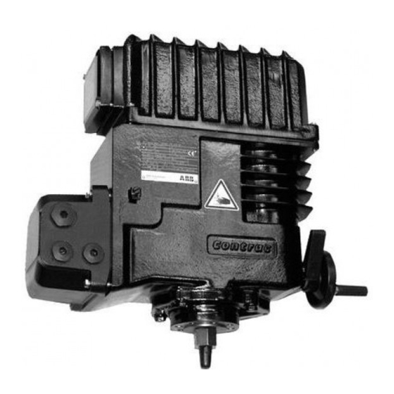
Figure 2: Mounting LME 620, example
7.3.1
Valve Design Requirements
- Consider the end position forces (up to 2.5 x rated force) when designing the valve.
7.4 Mounting the Actuator to the Valve
- Completely retract the actuator thrust rod and put the actuator on the valve yoke.
- Make sure the valve stem is centrically aligned with the bore and at right angles to
the actuator seat (permissible parallel deviation < 0.1 mm referred to total stroke).
- Fasten the actuator to the yoke with screws of property class 8.8 (tensile strength
2
800 N|mm
; yield strength 640 N/mm
- Use the handhweel to extend the thrust rod, link the rod with the valve stem via the
clutch.
- Manually retract the thrust rod to check whether or not the external stop of the ac-
tuator is on the housing flange before the valve cone gets in touch with the cover.
- If required, adjust with the clutch (only possible within certain limits!)
fastening scrrews
external limit stop
coupling
valve stem
valve yoke
valve
2
)
(r00018x1)
