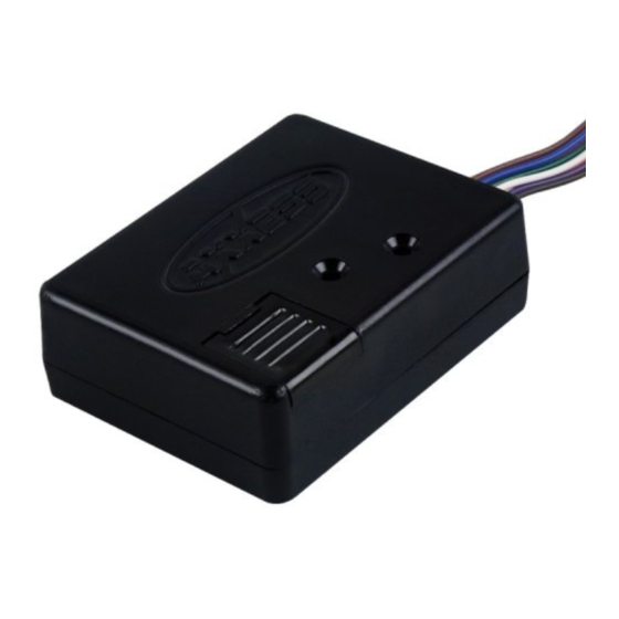
Axxess TRIGGER Installationsanleitung Handbuch - Seite 14
Blättern Sie online oder laden Sie pdf Installationsanleitung Handbuch für Automobilelektronik Axxess TRIGGER herunter. Axxess TRIGGER 19 Seiten.

Custom Mode 3: Delayed turn-off
Connect active high input to pin 9, or active low input to pin 10. Use any output
pin. When input goes high, output will turn on immediately. When input goes
inactive, output turn-off will be delayed by XX seconds, where XX is definable
between .1 and 300 seconds.
Connections:
Interface wiring
Pin 2 (Purple)
Pin 3 (White)
Pin 4 (Pink)
Pin 5 (Orange)
Pin 6 (Green)
Pin 7 (Red)
Pin 8 (Blue)
Pin 9 (Brown)
Pin 10 (Gray)
To
Ground
Ground
Ground
Ground
Negative latched output (500 mA max)
Negative latched output (500 mA max)
Positive latched output (2 amp max)
Positive pulse input (use only one)
Negative pulse input (use only one)
