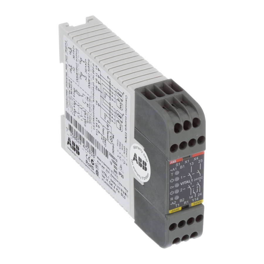
ABB vital 1 Original-Bedienungsanleitung - Seite 7
Blättern Sie online oder laden Sie pdf Original-Bedienungsanleitung für Controller ABB vital 1 herunter. ABB vital 1 20 Seiten. Safety controller
Auch für ABB vital 1: Handbuch (14 seiten)

3
Connections
Vital 1 electrical connections
NB: Shielded cable is recommended between this unit and the rest of the safety circuit.
NB: A switch to determine the functionality of the information output is located on the inside of the housing and can
be accessed by removing the top connection block. Information output functionality is described in the section
Output connections.
Warning! All power to the device must be disconnected before the connection blocks may be removed.
Warning! The information channel output shall never be used for the safety purpose(s).
Warning! The safety loops shall not be used for purposes other than intended. All loading or tampering with loops
can lead to serious risk of life.
Warning! Connection cables from ABB JOKAB Safety must be used in the safety circuit to ensure that no short
circuits of two inverted or non-inverted signals are possible within the connection cables. If other cables are used,
the installer must ensure that such short-circuits are not possible. Refer to EN ISO 13849-2 for details and support
on how to achieve this.
2TLC172156M0201, rev. C
2016-07-04
Upper connection block:
(7x terminals)
+A1: +24 VDC (external power supply)
S1:
Connect to B1 if EVEN number of sensors are
connected in series to Vital 1
B1:
+24 VDC (sensor/unit power supply)
X1:
Manually supervised reset
13:
Relay output 1 (13-14)
X4:
Automatic reset
23:
Relay output 2 (23-24)
Lower connection block:
(7x terminals)
-A2: 0 VDC (external power supply)
T1:
Dynamic signal output
B2:
0 VDC (sensor/unit power supply)
R1:
Dynamic signal input
14:
Relay output 1 (13-14)
Y14: Information output
24:
Relay output 2 (23-24)
7
www.abb.com/jokabsafety
