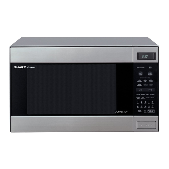
Sharp Carousel R-990C Service-Handbuch - Seite 10
Blättern Sie online oder laden Sie pdf Service-Handbuch für Mikrowellenherd Sharp Carousel R-990C herunter. Sharp Carousel R-990C 44 Seiten. Convection microwave oven
Auch für Sharp Carousel R-990C: Betriebshandbuch (40 seiten)

R-990C(S)
beyond the rated peak reverse voltage 1.7 KV in the
voltagedoubler circuit.
3. D2 of the rectifier is shorted.
4. The large electric currents flow through the high voltage
winding of the power transformer.
5. The large electric currents beyond 8A flow through the
primary winding of the power transformer.
6. The fuse M8A blows by the large electric currents.
7. The power supply to the power transformer is cut off.
THERMISTOR
The thermistor is a negative temperature coefficient type.
The temperature in the oven cavity is detected through the
resistance of the thermistor, and then the control unit
causes the heating element relay to operate, thus the
current to the heating element is turned ON/OFF.
MONITOR RESISTOR
The monitor resistor prevents the fuse M8A 250V bursting
when the fuse M8A 250V blows due to the operation of the
monitor switch.
TURNTABLE MOTOR
The turntable motor drives the turntable supporting plate
to rotate the turntable.
CONVECTION MOTOR
The convection motor drives the convection fan and
provides the heated air.
FAN MOTOR
The fan motor drives a blade which draws external cool air.
This cool air is directed through the air vanes surrounding
the magnetron and cools the magnetron. This air is chan-
nelled through the oven cavity to remove steam and
vapours given off from the heating foods. It is then ex-
hausted through the exhausting air vents at the oven
cavity.
CONVECTION HEATER
The convection heater is located at the rear of the oven
cavity. It is intended to heat air driven by the convection
fan. The heated air is kept in the oven and force-circulated
and reheated by the convection heater.
CONVECTION COOKING SYSTEM
This oven is designed with a hot air heating system where
food is not directly heated by the convection heater, but is
heated by forced circulation of the hot air produced by the
convection heater. The air heated by the convection
heater is circulated through the convection passage pro-
vided on the outer casing of the oven cavity by means of
the convection fan which is driven by the convection
motor. It then enters the inside of the oven through the vent
holes provided on the left side of the oven. Next, the hot air
heats the food on the turntable and leaves the oven cavity
through the vent in the oven cavity left side wall. Without
leaving the oven, this hot air is reheated by the convection
heater, passes through the convection passage and en-
ters the inside of the oven cavity again, in a continuing
cycle. In this way, the hot air circulates inside the oven
cavity to raise its temperature and, at the same time,
comes into contact with the food being cooked. When the
temperature inside the oven cavity reaches the selected
temperature, the convection heater is de-energized. When
the temperature inside the oven cavity drops below the
selected temperature, the convection heater is energized
again. In this way, the inside of the oven cavity is main-
tained at approximately the selected temperature.
When the convection time reaches 0, the convection
heater is de-energized and the convection fan stops
operating and the oven shuts off. Upon completion of the
cooking time, the audible signal will sound, and oven lamp,
turntable motor, cooling fan motor and convection motor
are de-energized. At the end of the convection cycle, if the
cavity air temperature is above 116˚C, the circuit to RY6
will be maintained (by the thermistor circuit) to continue
operation of the cooling fan motor until the temperature
drops below 116˚C, at which time the relay will be de-
energized, turning off the fan motor. Relay RY5 will how-
ever, open as soon as the convection cycle has ended,
turning off the convection fan motor. This will now cool and
allow the damper door to open.
DAMPER OPEN-CLOSE MECHANISM
Usually, the damper is in the open position except during
convection cooking.
Damper position is set automatically by damper motor,
damper switch, motor cam and damper shaft.
These components are operated by a signal that judges if
microwave cooking or convection cooking operation is
selected by the CPU unit.
Microwave Cooking:
Damper is in the open position, because a portion of
cooling air is channelled through the cavity to remove
steam and vapours given off from the heating foods.
It is then exhausted at the top of the oven cavity into a
condensation compartment.
Convection Cooking:
Damper is in the closed position, so that no hot air will be
allowed to leak out the oven cavity.
Damper Operation
1. When power supply cord is plugged in:
1-1. When power supply cord is plugged in, a signal is
sensed in the control unit, and operates shut-off relay
(RY4).
1-2. Contacts of shut-off relay (RY4) close, the damper
motor is energized, opening the damper door.
1-3. When the damper is moved to the open position by
the damper cam, damper switch is closed (ON
position).
1-4. The signal of damper switch is re-sensed in the
control unit and shut-off relay (RY4) is turned off.
1-5. The rated voltage to the damper motor is stopped and
the motor turns off.
2. When oven is microwave cooking:
Damper is in the open position
3. When oven is convection cooking:
3-1 Damper motor is energized by touching the convection,
temperature and START pads.
3-2. When damper is in the closed position (damper
switch is OFF), its signal is sensed by the control unit,
and shut-off relay (RY4) is de-energized.
3-3. The damper is held in the closed position during the
convection cooking operation.
3-4. At the end of the convection cooking, shut-off relay
8
