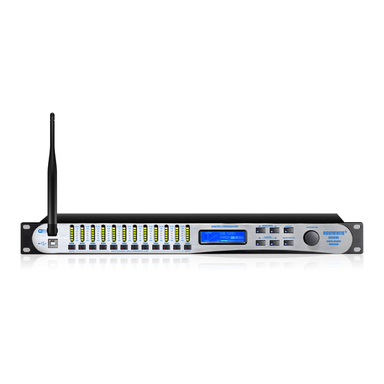
DIGISYNTHETIC DS224E(WiFi) Benutzerhandbuch - Seite 10
Blättern Sie online oder laden Sie pdf Benutzerhandbuch für Controller DIGISYNTHETIC DS224E(WiFi) herunter. DIGISYNTHETIC DS224E(WiFi) 10 Seiten. Digital loudspeaker management

Specifications
Number of Input Channel .........................................................................................................................................................
Number of Output Channel ...................................................................................................................................................
Input Impedance .....................................................................................................................................................................
Maximum Input Level .......................................................................................................................................................
Input CMRR .....................................................................................................................................................................
Input Sockets ......................................................................................................................................
Sampling Frequency ............................................................................................................................................................
Output Impedance .................................................................................................................................................................
Maximum Output Level .....................................................................................................................................................
Output Sockets .......................................................................................................................................
Input / Output Gain .................................................................................................................................................
Input / Output Delay ............................................................................................................................................
Input / Output PEQ Bands ............................................................................................................................................................
Input / Output PEQ Type .............................................................
Input / Output PEQ Frequency ............................................................................................................................
Input / Output PEQ Gain .......................................................................................................................................
Input / Output PEQ Bandwidth ............................................................................................................................
Input / Output GEQ Bands ..........................................................................................................................................................
Input / Output GEQ Frequency .............................................................................
Input / Output GEQ Gain .......................................................................................................................................
Input / Output Compressor Threshold .....................................................................................................................
Input / Output Compressor Ratio ....................................................................................................
Input / Output Compressor Attack-Time ......................................................................................................................
Input / Output Compressor Release-Time ................................................................................................................
Output High / Low-Pass Filter Frequency ...........................................................................................................
Output High / Low-Pass Filter Type ..........................................................................................
Output High / Low-Pass Filter Slope ................................................................................
Frequency Response ...................................................................................................................................
Dynamic Range ..........................................................................................................................................
Crosstalk ...........................................................................................................................................................................
THD+N .....................................................................................................................................................
Mains Input Voltage & Frequency ...............................................................................................................
Fuse Size ..............................................................................................................................................................
Power Rating .........................................................................................................................................................................
Dimensions .......................................................................................................................................................
Net Weight
........................... ..............................................................................................................................................
***The above design and specifications are subject to change without prior notice for product improvement.
..
PEQ, 6dB / 12 dB Low-Shelf, 6dB / 12 dB High-Shelf, Phase Shifter
1/3-Octave ISO Spacing From 19.7 Hz to 21.9 kHz
12dB/Oct, 24dB
9
+
> 55 dB
XLR-3Pin Female Connector
+20 dBu
XLR-3Pin Male Connector
-40dB ~ +12dB
0ms ~ 2000.02 ms
19.7 Hz ~ 21.9 kHz
-30 dB ~ +15 dB
0.017 ~ 4.750 Oct
-30 dB ~ +15 dB
-20 dB ~ +20 dB
1.2, 1.5, 2, 3, 4, 6, 10, 20, 40, 128
0 ms ~100ms
50 ms ~1000 ms
19.7 Hz ~ 21.9 kHz
Bessel, Butterworth, Linkwitz-Riley
/Oct
, 36dB
/Oct
, 48dB/Oct
20 Hz ~ 20 kHz ±0.1dB
> 112 dB (A-Weighting)
< 95 dB
< 0.004% (1kHz, 1Vrms)
90 V-250 Vac, 50/60 Hz
T1AL , AC250 V
482×218×45 (
4 / 2
8 / 6 / 4
8 kΩ
20 dBu
48 kHz
150 Ω
9
31
30 W
)
mm
3.6
kg
