Shimano CS-HG50-8I Handbuch - Seite 3
Blättern Sie online oder laden Sie pdf Handbuch für Zubehör für Fahrräder Shimano CS-HG50-8I herunter. Shimano CS-HG50-8I 5 Seiten. Rear drive system

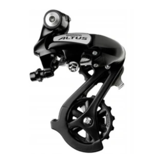
Installation of the rear derailleur
When installing, be careful that deformation is not caused by the B-tension
adjustment screw coming into contact with the dropout tab.
5 mm Allen key
Installation of the sprockets
For each sprocket, the
surface that has the group
mark should face outward
and be positioned so that
the triangle (U) mark on
each sprocket and the A
part (where the groove
width is wide) of the
freewheel body are aligned.
U mark
A
The groove is
wide at one
place only.
The 6 sprockets are secured by
means of rivets.
Chain length
Add 2 links (with the chain on both the largest
sprocket and the largest chainring)
Mounting the shifting lever
Bracket spindle tightening torque:
8 - 10 N·m {70 - 86 in. lbs.}
B-tension adjustment screw
Dropout tab
For installation of the HG sprockets, use the
special tool (TL-LR15) to tighten the lock ring.
Tightening torque:
30 - 50 N·m {261 - 434 in. lbs.}
To replace the HG sprockets, use the special
tool (TL-LR15) and TL-SR21 to remove the
lock ring.
Disassembly
Largest chainring
Chain
Use a handlebar grip with a maximum
outer diameter of 32 mm.
Allen key tightening torque:
6 - 8 N·m {53 - 69 in. lbs.}
5 mm Allen key
Lock ring
Tool
TL-LR15
(TL-SR21)
Lock ring
Largest chainring
