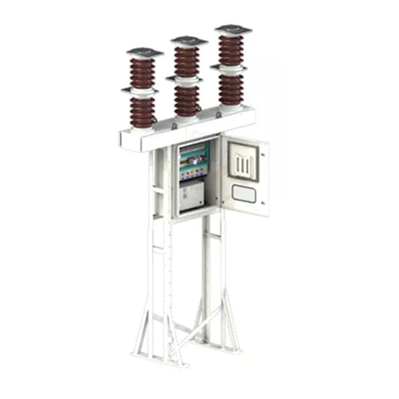
Siemens 3AF 01 Betriebsanleitung - Seite 15
Blättern Sie online oder laden Sie pdf Betriebsanleitung für Industrielle Ausrüstung Siemens 3AF 01 herunter. Siemens 3AF 01 24 Seiten. Outdoor vacuum switchgear

22
10
15
12
1
21
8
9
16
2
11
1. Gear box
2. Motor
3. Mechanical ON push
button
4. Closing solenoid
(release)
5. Tripping solenoid
(release)
6. Mechanical OFF push
button
7. Operating rod for snap
switches
8. Mechanical spring
charged indicator
9. Mechanical ON/OFF
indicator
Fig. 11 Details of operating mechanism
7.6
Space Heater in the operating mechanism
housing
CAUTION
Note : The heater must be always "ON" whether the
breaker is in service or not, to prevent condensation of
moisture particularly on the insulating components.
One heater is provided in the mechanism housing. Keep
the heater switch in the ON position, so that when the
control supply is applied all the heaters are ON.
NOTE
Keep door and all covers closed firmly to prevent entry
of dust, moisture, insects etc.
3
6
18 19
13
10. Sheet steel frame
11. Shock absorber
12. Closing spring
13. Tripping spring
14. Auxiliary switch
15. Opening for hand crank
16. Operation counter
17. Drive shaft
18. Pin
19. Damping plates
20. Additional releases
(optional)
21. Snap switch
22. Rating plate
23. Tie rod for aux. switch
7.7
Inert Gas in the Sealed Pole
(optional feature)
Inert gas N
is filled up in each pole at about 1.5 bar
2
during manufacturing, in order to prevent the entry and
subsequent condensation of moisture during the service
life of the breaker. The gas is not for the purpose of
insulation.
14
4
5
3.
Pin
4.
Shaft
20
23
17
28.1
Fig. 12A Cross section of base frame
28. Indicator
28.1 Erosin Scale
28
4
3
13
