Siemens Simatic S7-300 Handbuch - Seite 12

Blättern Sie online oder laden Sie pdf Handbuch für Industrielle Ausrüstung Siemens Simatic S7-300 herunter. Siemens Simatic S7-300 32 Seiten. Automation systems, controlling a physical axis
Auch für Siemens Simatic S7-300: Benutzerhandbuch (34 seiten), Handbuch (21 seiten), Betriebsanleitung (4 seiten), Betriebsanleitung (5 seiten), Handbuch (35 seiten), Erste Schritte (8 seiten), Erste Schritte (16 seiten), Beschreibung der Anwendung (24 seiten), Handbuch (18 seiten), Installations- und Hardware-Handbuch (20 seiten), Erste Schritte (32 seiten)
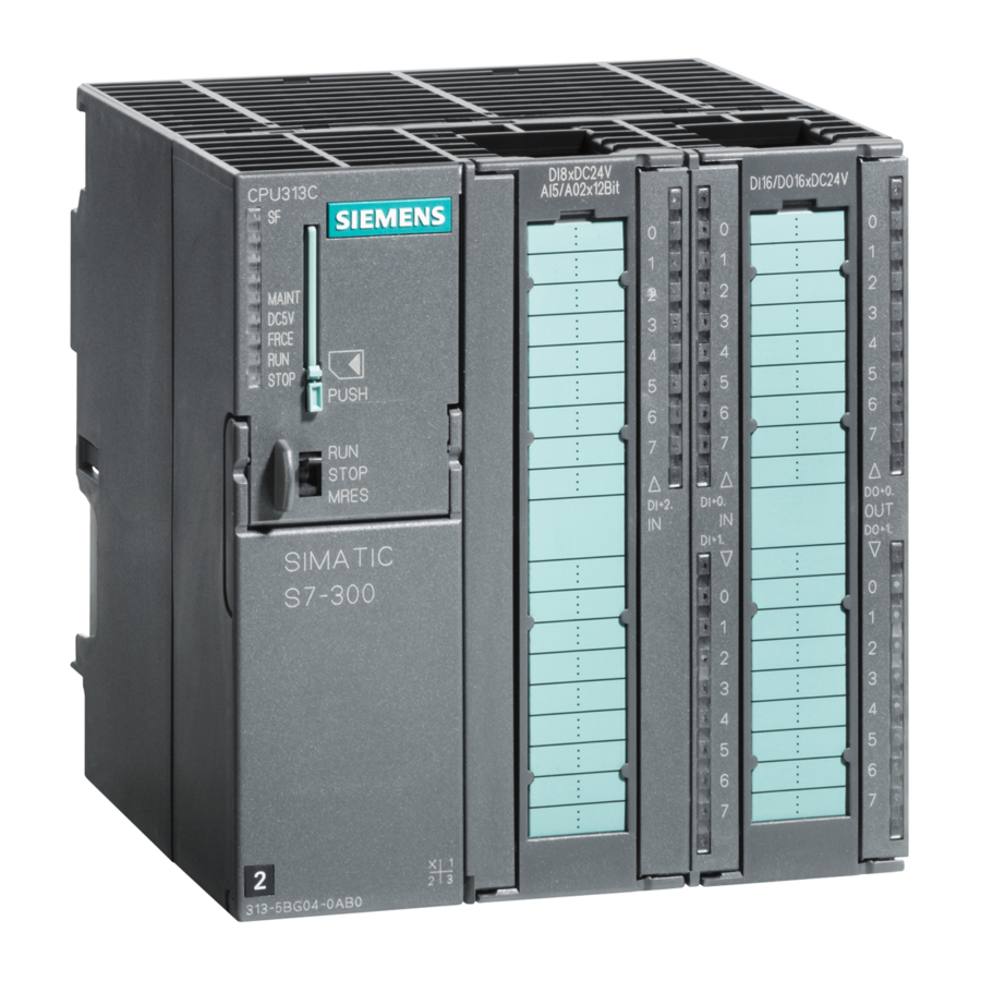
Siemens Simatic S7-300 Handbuch
1.4
Interrupts of the SM 321; DI 16
Introduction
This section describes the interrupt behavior of the SM 321; DI 16
following interrupts exist:
S Diagnostic interrupt
S Hardware interrupt
The OBs and SFCs mentioned below can be found in the online Help for STEP 7,
where they are described in greater detail.
Enabling interrupts
The interrupts are not preset – in other words, they are inhibited without
appropriate parameter assignment. Assign parameters to the Interrupt Enable in
STEP 7 (refer to Section 1.2).
Diagnostic interrupt
If you have enabled diagnostic interrupts, then active error events (initial
occurrence of the error) and departing error events (message after
troubleshooting) are reported by means of an interrupt.
The CPU interrupts the execution of the user program and processes the
diagnostic interrupt block (OB 82).
In the user program, you can call SFC 51 or SFC 59 in OB 82 to obtain more
detailed diagnostic information from the module.
The diagnostic information is consistent until such time as OB 82 is exited. When
OB 82 is exited, the diagnostic interrupt is acknowledged on the module.
Hardware interrupt
The SM 321; DI 16
group at a rising edge, a falling edge, or at both edges of a signal status change.
Perform parameter assignment one channel group at a time. It can be modified at
any time (in RUN mode using the user program).
Pending hardware interrupts trigger hardware interrupt processing in the CPU
(OB 40). The CPU interrupts the execution of the user program or of the priority
classes with low priority.
You can set in the user program of the hardware interrupt OB (OB 40) how the
programmable logic controller has to react to an edge change. When the hardware
interrupt OB is exited, the hardware interrupt is acknowledged on the module.
The module can buffer one interrupt per channel. If no higher priority run-time
levels are waiting to be processed, the buffered interrupts (of all modules) are
serviced one after the other by the CPU according to the order in which they
occurred.
12
DC 24 V can trigger a hardware interrupt for every channel
Product Information on the Manual S7-300 Module Specifications, Edition 11/2002
DC 24 V
DC 24 V. The
A5E00213444-02