Siemens SINAMICS G120 Betriebsanleitung - Seite 24

Blättern Sie online oder laden Sie pdf Betriebsanleitung für Industrielle Ausrüstung Siemens SINAMICS G120 herunter. Siemens SINAMICS G120 32 Seiten. Using blocksize converters in marine applications
Auch für Siemens SINAMICS G120: Erste Schritte (46 seiten), Erste Schritte (30 seiten), Hardware-Installationsanleitung (2 seiten), Installationsanleitung und Benutzerhandbuch (2 seiten), Einbauanleitung (2 seiten), Einbauanleitung (2 seiten), Kompakt-Bedienungsanleitung (32 seiten), Handbuch (42 seiten), Erste Schritte (50 seiten), Gerätehandbuch (34 seiten), Handbuch zur Schnellinstallation (2 seiten), Beschreibung der Anwendung (50 seiten), Kompakt-Bedienungsanleitung (2 seiten), Handbuch (31 seiten), Anwendungshandbuch (34 seiten), Kompakt-Bedienungsanleitung (2 seiten), Kompakt-Bedienungsanleitung (2 seiten)
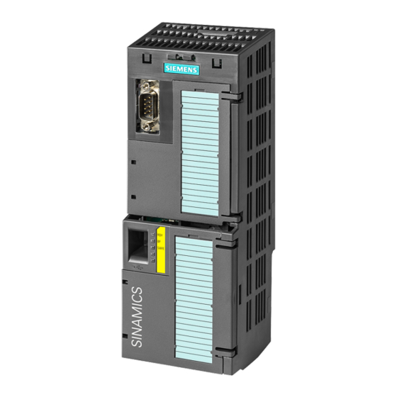
Siemens SINAMICS G120 Betriebsanleitung
Commissioning

4.2 Connecting the inverter to the fieldbus

4.2
Connecting the inverter to the fieldbus
Where can I find instructions for the fieldbus connection of the inverter?
Instructions for connecting to a fieldbus can be downloaded from the Internet:
● Application examples (http://support.automation.siemens.com/WW/view/en/60733299)
● Operating Instructions: CU250S-2 operating instructions
(https://support.industry.siemens.com/cs/ww/en/view/109478829)
● "Fieldbuses" function manual: Manuals for the Control Unit
(http://support.automation.siemens.com/WW/view/en/30563628/133300)
Example telegram
Telegram 1
Further information is provided in the Internet:
● Operating Instructions: Inverter telegrams without configured basic positioner
● "Basic positioner" function manual: Telegrams with configured basic positioner
Manuals for the Control Unit
(http://support.automation.siemens.com/WW/view/en/30563628/133300).
Control word 1 (STW1), PZD receive word 1 (word: r2050[0], bits: r2090.00 ... r2090.15)
Bit
Meaning
0
0 = OFF1
0 → 1 = ON
1
0 = OFF2
1 = No OFF2
2
0 = Quick stop (OFF3)
1 = No quick stop (OFF3)
3
0 = Inhibit operation
1 = Enable operation
24
Explanation
The motor brakes with the ramp-down time p1121 of the ramp-function generator. The
inverter switches off the motor at standstill.
The inverter goes into the "ready" state. If, in addition bit 3 = 1, then the inverter
switches on the motor.
Switch off the motor immediately, the motor then coasts down to a standstill.
Precondition in order to be able to switch on the motor using bit 0 (ON command).
The motor brakes with the OFF3 ramp-down time p1135 down to standstill.
Precondition in order to be able to switch on the motor using bit 0 (ON command).
Switch off the motor immediately → motor coasts down to a standstill.
Precondition in order to be able to switch on the motor using bit 0 (ON command).
Abbreviation
Explanation
STW1
Control word 1
ZSW1
Status word 1
PZD01/02
Process data 16-bit
NSOLL_A
Speed setpoint 16-bit
NIST_A
Actual speed value 16-bit
Compact Operating Instructions, 01/2016, A5E37058195B AA
CU250S-2 Control Units