Siemens SINAMICS G120 Kompakt-Bedienungsanleitung - Seite 20

Blättern Sie online oder laden Sie pdf Kompakt-Bedienungsanleitung für Industrielle Ausrüstung Siemens SINAMICS G120 herunter. Siemens SINAMICS G120 32 Seiten. Using blocksize converters in marine applications
Auch für Siemens SINAMICS G120: Erste Schritte (46 seiten), Betriebsanleitung (32 seiten), Erste Schritte (30 seiten), Hardware-Installationsanleitung (2 seiten), Installationsanleitung und Benutzerhandbuch (2 seiten), Einbauanleitung (2 seiten), Einbauanleitung (2 seiten), Handbuch (42 seiten), Erste Schritte (50 seiten), Gerätehandbuch (34 seiten), Handbuch zur Schnellinstallation (2 seiten), Beschreibung der Anwendung (50 seiten), Kompakt-Bedienungsanleitung (2 seiten), Handbuch (31 seiten), Anwendungshandbuch (34 seiten), Kompakt-Bedienungsanleitung (2 seiten), Kompakt-Bedienungsanleitung (2 seiten)
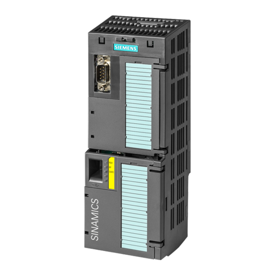
Siemens SINAMICS G120 Kompakt-Bedienungsanleitung
Commissioning
4.2 Commissioning with BOP-2 operator panel
Selecting a suitable application class
When selecting an application class, the inverter assigns the appropriate settings to the
motor control.
Application class
Motors that can be
operated
Power Modules that
can be operated
Application examples
Properties
Max. output frequency
Torque control
Commissioning
20
Standard Drive Control
Induction motors
Pumps, fans, and compressors with flow
characteristic
Wet or dry blasting technology
Mills, mixers, kneaders, crushers, agitators
Horizontal conveyor technology (conveyor
belts, roller conveyors, chain conveyors)
Basic spindles
Typical correction time after a speed
change: 100 ms ... 200 ms
Typical correc-
tion time after a
load surge:
500 ms
Standard Drive
Control is suita-
ble for the fol-
lowing require-
ments:
Motor power
ratings < 45 kW
Acceleration time 0 → rated speed (de-
pending on the rated motor power):
1 s (0.1 kW) ... 10 s (45 kW)
Applications with increasing load torque
without load surges
Standard Drive Control is insensitive with
respect to inaccurate motor data settings
240 Hz
Without torque control
Contrary to "Dynamic Drive Control" a
speed controller does not have to be set
In comparison to "Configuration for experts":
Simplified commissioning using preas-
signed motor data
Reduced number of parameters
Induction and synchronous motors
PM240, PM240-2, PM340
Pumps and compressors with displacement
machines
Rotary furnaces
Extruder
Centrifuge
Typical correction time after a speed
change: < 100 ms
Typical correction
time after a load
surge: 200 ms
Dynamic Drive
Control controls
and limits the mo-
tor torque
Torque accuracy
that can be
achieved: ± 5 %
for 15 % ... 100 % of the rated speed
We recommend Dynamic Drive Control for
the following applications:
Motor power ratings > 11 kW
For load surges of 10 % ... >100 % of
the rated motor torque
Dynamic Drive Control is necessary for an
acceleration time 0 → rated speed (depend-
ent on the rated motor power):
< 1 s (0.1 kW) ... < 10 s (250 kW).
Speed control with lower-level torque control
Reduced number of parameters when com-
pared to "Configuration for experts"
Compact Operating Instructions, 04/2015, A5E35792002B AA
Dynamic Drive Control
200 Hz
CU240B-2 and CU240E-2 Control Units