Siemens SINAMICS G120 Kompakt-Bedienungsanleitung - Seite 30

Blättern Sie online oder laden Sie pdf Kompakt-Bedienungsanleitung für Industrielle Ausrüstung Siemens SINAMICS G120 herunter. Siemens SINAMICS G120 32 Seiten. Using blocksize converters in marine applications
Auch für Siemens SINAMICS G120: Erste Schritte (46 seiten), Betriebsanleitung (32 seiten), Erste Schritte (30 seiten), Hardware-Installationsanleitung (2 seiten), Installationsanleitung und Benutzerhandbuch (2 seiten), Einbauanleitung (2 seiten), Einbauanleitung (2 seiten), Handbuch (42 seiten), Erste Schritte (50 seiten), Gerätehandbuch (34 seiten), Handbuch zur Schnellinstallation (2 seiten), Beschreibung der Anwendung (50 seiten), Kompakt-Bedienungsanleitung (2 seiten), Handbuch (31 seiten), Anwendungshandbuch (34 seiten), Kompakt-Bedienungsanleitung (2 seiten), Kompakt-Bedienungsanleitung (2 seiten)
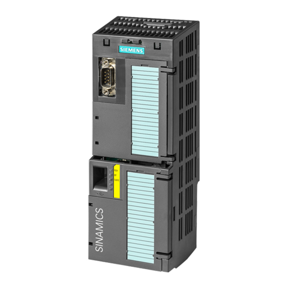
Siemens SINAMICS G120 Kompakt-Bedienungsanleitung
Commissioning
4.4 Frequently required parameters
Parameter
Explanation
p0776
Analog outputs, type
[0]
AO 0
[1]
AO 1
p0922
PROFIdrive telegram selection
p1001
Fixed speed setpoint 1
p1002
Fixed speed setpoint 2
p1003
Fixed speed setpoint 3
p1004
Fixed speed setpoint 4
p1058
Jog 1 speed setpoint
p1059
Jog 2 speed setpoint
p1070
Main setpoint
p1080
Minimum speed [rpm]
p1082
Maximum speed [rpm]
p1120
Ramp-function generator ramp-up time [s]
p1121
Ramp-function generator ramp-down time [s]
p1300
Open-loop/closed-
loop control oper-
ating mode
p1310
Starting (voltage boost) permanent
p1800
Pulse frequency setpoint
p2030
Fieldbus interface protocol selection
r2050
Words received via fieldbus (16 bit)
r2050[0]: PZD01 ... r2050[11]: PZD12
p2051
Words sent via fieldbus (16 bit)
p2051[0]: PZD01 ... p2051[16]: PZD17
p2080
Binector-connector converter, status word 1
p2080[0]: Bit 0 ... p2080[15]: Bit 15
r2090
PROFIdrive PZD1 receive bit-by-bit (control word 1)
r2090.00: Bit 0 ... r2090.15: Bit 15
30
0: Current output (0 mA ... +20 mA)
1: Voltage output (0 V ... +10 V)
2: Current output (+4 mA ... +20 mA)
Selection of the possible settings:
0: Main setpoint = 0
755[0]: Analog input 0
1024: Fixed setpoint
Selection of the possible settings:
0: U/f control with linear characteristic
1: U/f control with linear characteristic and FCC
2: U/f control with parabolic characteristic
1050: Motorized potentiometer
2050[1]: PZD 2 from the fieldbus
20: Speed control (without encoder)
22: Torque control (without encoder)
The possible settings depend on the Control Unit:
0: No protocol
1: USS
2: Modbus RTU
3: PROFIBUS
4: CANopen
Compact Operating Instructions, 04/2015, A5E35792002B AA
5: BacNet
7: PROFINET
8: P1
10: EtherNet/IP
CU240B-2 and CU240E-2 Control Units