Siemens SINAMICS G120 Erste Schritte - Seite 32

Blättern Sie online oder laden Sie pdf Erste Schritte für Industrielle Ausrüstung Siemens SINAMICS G120 herunter. Siemens SINAMICS G120 50 Seiten. Using blocksize converters in marine applications
Auch für Siemens SINAMICS G120: Erste Schritte (46 seiten), Betriebsanleitung (32 seiten), Erste Schritte (30 seiten), Hardware-Installationsanleitung (2 seiten), Installationsanleitung und Benutzerhandbuch (2 seiten), Einbauanleitung (2 seiten), Einbauanleitung (2 seiten), Kompakt-Bedienungsanleitung (32 seiten), Handbuch (42 seiten), Gerätehandbuch (34 seiten), Handbuch zur Schnellinstallation (2 seiten), Beschreibung der Anwendung (50 seiten), Kompakt-Bedienungsanleitung (2 seiten), Handbuch (31 seiten), Anwendungshandbuch (34 seiten), Kompakt-Bedienungsanleitung (2 seiten), Kompakt-Bedienungsanleitung (2 seiten)
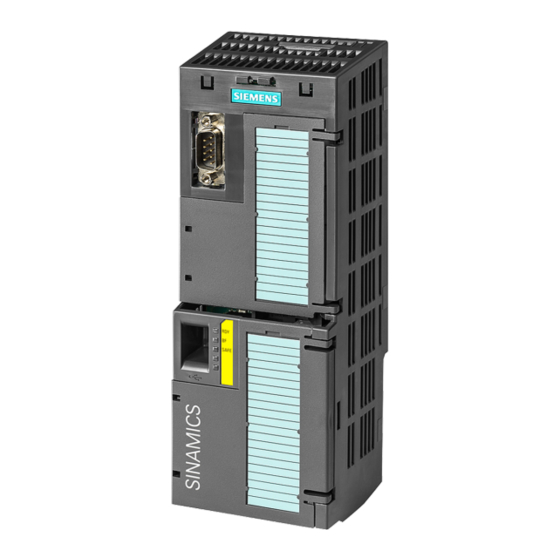
Siemens SINAMICS G120 Erste Schritte
Installing
3.3 Installing Control Unit
3.3.4

Wiring the terminal strip

NOTICE
Damage to the inverter when using long signal cables
Using long cables at the inverter's digital inputs and 24 V power supply can lead to
overvoltage during switching operations. Overvoltages can damage the inverter.
• If you use cables of more than 30 m at the digital inputs and 24 V power supply, connect
Procedure
Proceed as follows to connect the terminal strips:
1. Use a cable with the recommended cross-section, which has been appropriately prepared
for use:
2. If you use shielded cables, then you must connect the shield to the mounting plate of the
control cabinet or with the shield support of the inverter through a good electrical
connection and a large surface area.
See also:EMC installation guideline
(http://support.automation.siemens.com/WW/view/en/60612658)
3. Use the shield connection plate of the Control Unit as strain relief, also see:Overview of
the shield connection kits
(http://support.automation.siemens.com/WW/news/en/67225884).
You have connected the terminal strip.
32
an overvoltage protection element between the terminal and the associated reference
potential.
We recommend using the Weidmüller overvoltage protection terminal with designation
MCZ OVP TAZ DIODE 24VDC.
Solid or flexible cable
Flexible conductor with non-insulated end sleeve
Flexible conductor with partially-insulated end sleeve
Only permitted for CU240B/E-2:
Two flexible cables with the same cross-section with partially
insulated twin end sleeves
Converter with Control Units CU230P-2; CU240B-2; CU240E-2
Getting Started, 04/2014, A5E32885834B AB