Siemens SINAMICS G130 Betriebsanleitung - Seite 32

Blättern Sie online oder laden Sie pdf Betriebsanleitung für Industrielle Ausrüstung Siemens SINAMICS G130 herunter. Siemens SINAMICS G130 38 Seiten. Line filter
Auch für Siemens SINAMICS G130: Betriebsanleitung (24 seiten), Betriebsanleitung (26 seiten), Betriebsanleitung (46 seiten), Betriebsanleitung (24 seiten), Betriebsanleitung (31 seiten), Betriebsanleitung (30 seiten), Betriebsanleitung (28 seiten), Betriebsanleitung (30 seiten), Betriebsanleitung (22 seiten), Betriebsanleitung (28 seiten), Betriebsanleitung (30 seiten), Betriebsanleitung (34 seiten), Betriebsanleitung (46 seiten), Betriebsanleitung (26 seiten), Betriebsanleitung (26 seiten), Betriebsanleitung (28 seiten), Betriebsanleitung (42 seiten), Betriebsanleitung (46 seiten), Betriebsanleitung (24 seiten), Betriebsanleitung (24 seiten), Betriebsanleitung (30 seiten), Betriebsanleitung (42 seiten), Betriebsanleitung (46 seiten), Betriebsanleitung (28 seiten), Betriebsanleitung (22 seiten), Betriebsanleitung (24 seiten)
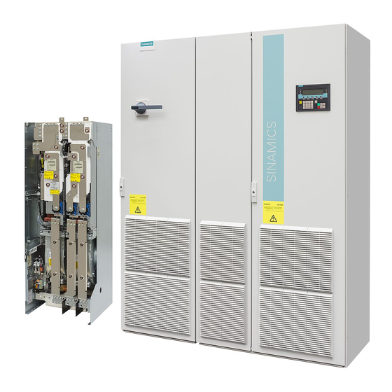
Siemens SINAMICS G130 Betriebsanleitung
Technical specifications
Detailed technical data
Table 6- 2
Technical data for the dv/dt filter plus Voltage Peak Limiter, 3 AC 380 V ... 480 V
Article number
Suitable for Power Module
Unit rating of the Power
Module
I
thmax
Degree of protection
dv/dt reactor
Power loss
- at 50 Hz
- at 60 Hz
- at 150 Hz
Connections
- to the Power Module
- Load
- PE
Max. permissible cable
length between dv/dt reactor
and motor
Dimensions
Width
Height
Depth
Weight, approx.
Voltage Peak Limiter
Power loss
- at 50 Hz
- at 60 Hz
- at 150 Hz
Connections
- to the dv/dt reactor
- DC
- PE
Dimensions
Width
Height
Depth
Weight, approx.
Two dv/dt reactors are required for these dv/dt filters. The technical data provided applies to one dv/dt reactor.
1)
Note
Cable lengths for versions with 2 dv/dt reactors
For versions with two dv/dt reactors, the cable lengths specified in the table do not change.
30
6SL3000-
2DE32-6AA0
6SL3310-
1GE32-1AA3
1GE32-6AA3
kW
110
132
A
260
IP00
kW
0.701
kW
0.729
kW
0.78
M10
M10
M6
m
mm
410
mm
370
mm
229
kg
66
kW
0.029
kW
0.027
kW
0.025
M8
M8
M8
mm
263
mm
265
mm
188
kg
6
2DE35-0AA0
2DE38-4AA0
1GE33-1AA3
1GE36-1AA3
1GE33-8AA3
1GE37-5AA3
1GE35-0AA3
1GE38-4AA3
160
200
250
490
IP00
0.874
0.904
0.963
M12
M12
M6
300 (shielded)
450 (unshielded)
460
370
275
122
0.042
0.039
0.036
Terminal 70 mm²
Terminal 70 mm²
Terminal 35 mm²
392
285
1312.5
210
16
Operating Instructions, 11/2017, A5E00692302A
2DE41-4AA0
1GE41-0AA3
315
560
400
450
840
1405
IP00
IP00
1.106
1.111
1.115
1.154
1.226
1.23
M12
2 x M12
M12
2 x M12
M6
M6
460
445
385
385
312
312
149
158
0.077
0.134
0.072
0.125
0.066
0.114
M8
M10
M8
M10
M8
M8
309
309
1312.5
400
400
48
72
dV/dt filter plus Voltage Peak Limiter
1