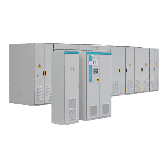
Siemens SINAMICS GL150 Referenzhandbuch - Seite 5
Blättern Sie online oder laden Sie pdf Referenzhandbuch für Industrielle Ausrüstung Siemens SINAMICS GL150 herunter. Siemens SINAMICS GL150 38 Seiten. Medium-voltage drive
Auch für Siemens SINAMICS GL150: Referenzhandbuch (44 seiten)

Table of contents
1
Introduction...................................................................................................................................................7
2
General scope of services ............................................................................................................................9
2.1
Routine test ............................................................................................................................11
2.2
Visual inspection ....................................................................................................................12
2.3
Function tests.........................................................................................................................13
2.4
Insulation test .........................................................................................................................14
2.5
Interface test ..........................................................................................................................15
3
Tests...........................................................................................................................................................17
3.1
Visual inspection ....................................................................................................................18
3.1.1
Rating plate ............................................................................................................................18
3.1.2
Housing degree of protection .................................................................................................18
3.1.3
Electrical cabinet components ...............................................................................................19
3.1.4
Cable installation....................................................................................................................19
3.1.5
Cable markings ......................................................................................................................20
3.1.6
Setting values of circuit breakers, if used...............................................................................20
3.1.7
Dimensions ............................................................................................................................20
3.2
Function test...........................................................................................................................22
3.2.1
Auxiliary voltages ...................................................................................................................22
3.2.2
Temperature monitoring in the control cabinet.......................................................................22
3.2.3
Redundant 230 V or 24 V auxiliary voltage supply ................................................................23
3.2.4
DC-link pulsed operation at 0 Hz ...........................................................................................23
3.2.5
DC-link pulsed operation at 2 Hz ...........................................................................................23
3.2.6
Line undervoltage...................................................................................................................24
3.2.7
Door limit switches .................................................................................................................24
3.2.8
Safety shutdown.....................................................................................................................25
3.3
Cooling system test................................................................................................................26
3.3.1
Air flow direction.....................................................................................................................26
3.3.2
Air pressure monitoring ..........................................................................................................26
3.4
Insulation test .........................................................................................................................27
3.4.1
High-voltage test ....................................................................................................................27
3.4.2
Measuring the insulation resistance.......................................................................................28
3.5
Interface test ..........................................................................................................................29
3.5.1
PROFIBUS communication....................................................................................................29
3.5.2
Signals to the customer's system...........................................................................................29
3.5.3
Additional interfaces...............................................................................................................30
Index...........................................................................................................................................................31
SINAMICS GL150 6SL3850 F03 F70 F98 E11
Reference Manual Rev.201902141420 GL150 luftgekühlt
5
